
 英語
英語 中文简体
中文简体 Русский
 Español
 Português
 Türkçe
 العربية
 Deutsch
 Polski
 Italiano
 Français
 한국어
한국어 ไทย
ไทย Tiếng Việt
 日本語
日本語





























吸収クランプ
ユーザーズマニュアル
適用 LISUN モデル: AB-CLP
1. 機器の基本的な理解
1.1製品の概要
1.1.1 主なパラメータ
| 技術パラメータ | インジケータ | Notes |
| 周波数範囲 | 30 MHz〜1000 MHz | Rated Operating Frequency Band |
| 出力インピーダンス | 50 Ω | Matching Coaxial System |
| Allowed cable diameter for testing | ≦20 mm | Exceeding the specifications may damage the equipment. |
| 信号コネクタ | タイプN | 出力ポート |
| Absorption Clamp Factor CF | -4 dB~4 dB | That is, the correction factor K varies with frequency |
| Decoupling Factor (DF) | ≥21デシベル | Ensure isolation between the test side and the power supply side |
| デカップリング係数 DR | ≥30デシベル | Decoupling Capability of Coaxial Cable Shielding |
| 寸法 | 640 mm(L)×109 mm(W)×100 mm(H) | |
| 重量 | 5キロ | |
1.1.2アプリケーションシナリオ
その AB-CLP Absorbing Clamp (ACA) is a specialized device used for disturbance power testing in the field of electromagnetic compatibility (EMC) and serves as an alternative measurement device for radiated emission testing. By coupling and extracting common-mode disturbance power from the cable under test, it indirectly evaluates the device’s radiated emission levels. Since it does not require a large anechoic chamber, it can significantly reduce testing costs and shorten testing cycles, and is widely used in product R& D debugging and pre-compliance testing scenarios.
1.2 Scope of Application and Basis for Standards
1.2.1 Equipment and Method Standards
The performance of this system’s equipment and the test methods fully comply with the following international and national standards:
Equipment Specifications: CISPR 16-1-3, GB/T 6113.103 (Specifications for Equipment for the Measurement of Radio Disturbance and Immunity—Part 3: Equipment for the Measurement of Disturbance Power)
Test Method Standards: CISPR 16-2-2, GB/T 6113.202 (Methods for Measuring Radio Disturbance and Immunity—Part 2: Measurement of Disturbance Power)
1.2.2 Applicable Products and Test Frequencies
The absorption clamp method is primarily used to evaluate electromagnetic interference radiated by equipment through power and signal lines. The mandatory test frequency bands vary depending on the product standard:
The 30 MHz to 300 MHz frequency range (which provides full coverage when used with the EMI-9KB)
is the mandatory compliance testing range for the vast majority of products. The corresponding product standards include:
CISPR 14-1 / GB 4343.1: Electromagnetic Compatibility—Emission Requirements for Household Appliances, Power Tools, and Similar Equipment; CISPR 15 / GB 17743: Radio Disturbance Characteristics of Electrical Lighting and Similar Equipment.
300 MHz to 1000 MHz (requires use with the EMI-9KC 受信機)
その AB-CLP Absorbing Clamp has a rated frequency range of 30 MHz to 1000 MHz, while the EMI-9KC receiver has an upper frequency limit of 1000 MHz.
When testing products such as audio-video receivers and multimedia devices (in accordance with standards such as CISPR 13 and CISPR 32), the standards require evaluation of disturbance power across the entire 30 MHz to 1000 MHz frequency band.
1.3 機器構成の検証
1.3.1開梱
When unpacking the device, handle it gently to avoid scratching the exterior with sharp tools. After unpacking, first inspect the exterior of the device to ensure there is no visible deformation or dents, and that the buttons are not damaged or loose. If you notice any abnormalities with the device or its accessories, please contact us immediately.
1.3.2 本体および付属品
図1-1を参照してください。
| 数 | お願い |
| ① | AB-CLP 吸収クランプ |
| ② | 同軸ケーブル |
| ③ | 6 dB同軸アッテネータ |
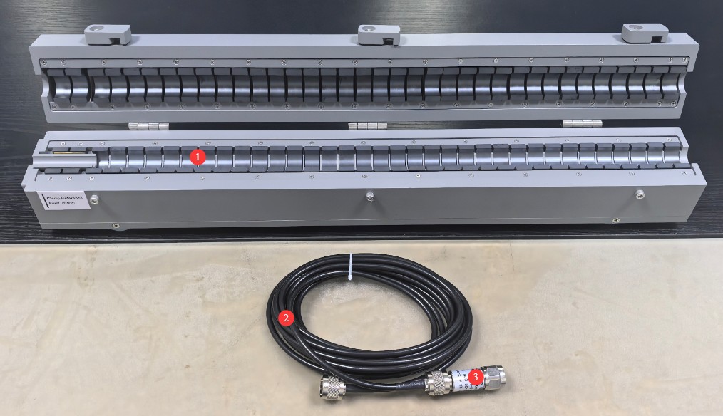
図1-1
1.3.3 電子文書のダウンロード
Links to the electronic user manual, warranty card, calibration certificate, and other documents have been sent via email. If you missed the email, please contact us to receive the links again.
2.安全上の注意
2.1 電気安全
The device under test and the receiver must each be connected to the power grid via an Isolation Transformer that meets the appropriate specifications. Direct connection to the mains power supply is strictly prohibited to prevent power surges and the risk of electric shock.
A separate and reliable grounding system must be installed; the lower the grounding resistance, the more accurate the test results will be. Sharing a grounding electrode with high-power electrical equipment is strictly prohibited, and the grounding terminals of all equipment must be securely connected to the grounding electrode.
Do not use the equipment if the power connections are loose or the cable sheath is damaged; during thunderstorms, disconnect all equipment from the power source and ground connections to prevent damage from lightning strikes.
The receiver’s RF input port is a sensitive RF interface; do not connect high-voltage or high-level signals directly to it, as this may damage the internal circuitry.
2.2操作上の安全性
Strictly follow the sequence: “Turn on the peripherals first, then the computer; turn off the computer first, then the peripherals.”
Before powering on or off the device under test, you must first disconnect the coaxial cable from the front end of the receiver to prevent switching transients from damaging the receiver’s internal circuitry; under no circumstances should you plug in or unplug the coaxial cable during testing.
When opening and closing the Absorbing Clamps, operate them smoothly to avoid pinching your hands; do not insert cables or hard metal objects with a diameter greater than 20 mm into the jaws to prevent the internal ferrite cores from cracking.
During testing, move the absorption clamp by gently pushing and pulling it to avoid violent impacts with the slide rail, thereby preventing displacement of the internal components that could affect test accuracy.
Unless authorized by the manufacturer, do not disassemble the casing of the absorption clamp or the receiver unit; otherwise, your warranty will be void.
2.3 環境安全
The equipment operating environment temperature is 5–35°C, with a relative humidity of ≤80% and no condensation; flammable, explosive, or corrosive materials must not be stored in the test area.
It is recommended that formal testing be conducted in an electromagnetically shielded room; for preliminary testing, select a separate room located far from sources of strong electromagnetic interference—such as variable-frequency drives, arc welders, high-power chargers, and wireless transmitting equipment—to minimize the impact of environmental background noise.
The test area must be at least 0.8 m away from walls and other large conductive objects to prevent electromagnetic wave reflections from affecting the test results.
3. Introduction to Auxiliary Equipment and System Wiring
3.1 EMI-9KB 受信機
3.1.1フロントパネル
図3-1を参照してください。
| 数 | お願い |
| ① | 電源スイッチ |
| ② | RF input port, connected to the AB-CLP using a coaxial attenuator and coaxial cable |
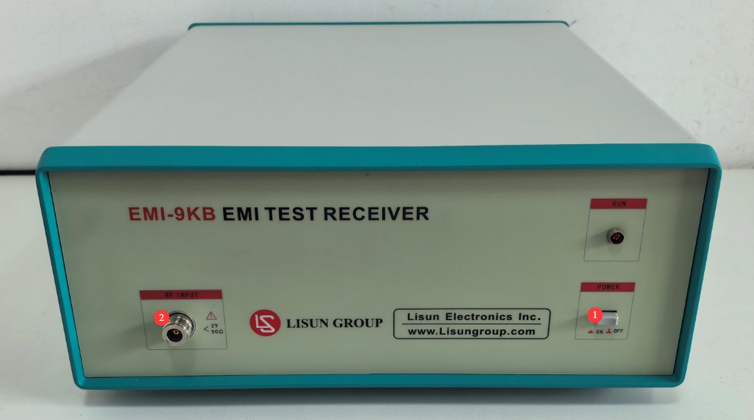
図3-1
3.1.2リアパネル
図3-2を参照してください。
| 数 | お願い |
| ① | Power cord jack, connected to an Isolation Transformer |
| ② | ヒューズ |
| ③ | RS-232 communication port: Connect to a computer using an RS-232 cable. If the computer does not have an RS-232 port, you can use the standard RS-232-to-USB adapter cable to connect to the computer. Note: Do not use non-standard cables or adapters, as this may cause communication errors. |
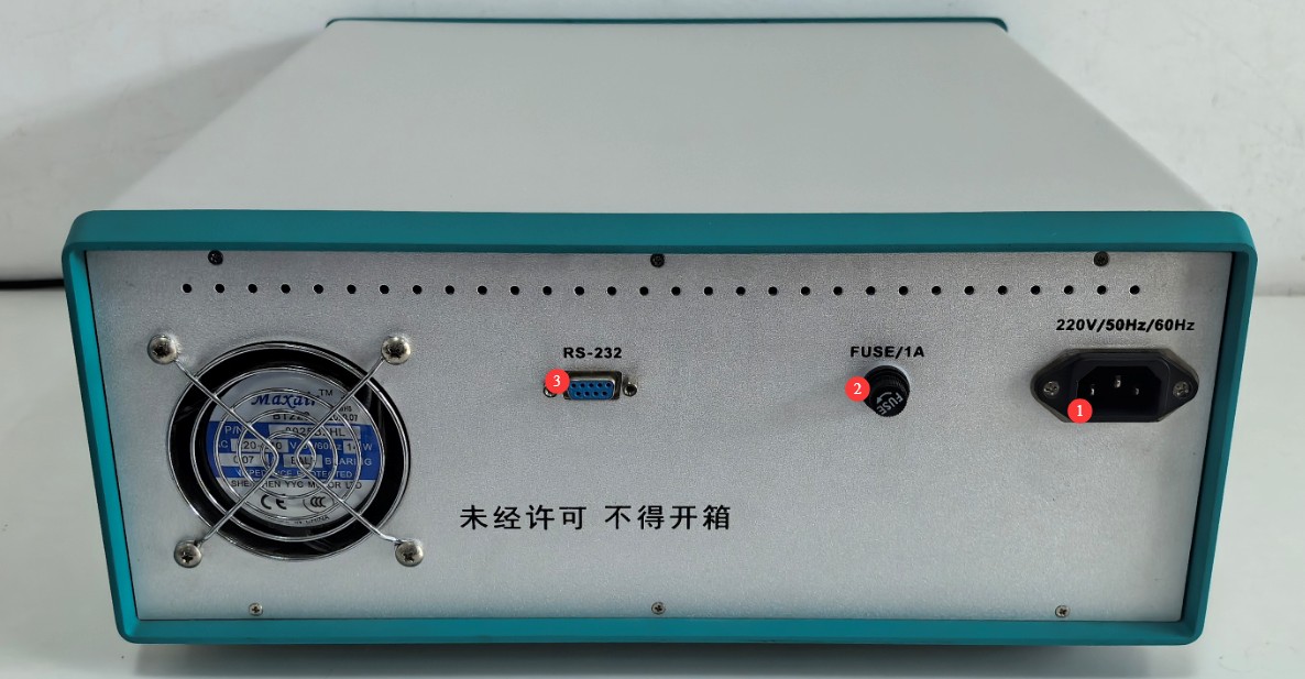
図3-2
3.2 Test System Wiring Procedure
Please complete the system wiring in the following order to ensure reliable connections.
| 配線手順 | お願い |
| ① Power Supply Circuit Wiring | Connect Isolation Transformer 1 to the mains power supply; use its output to connect the power supply circuit for the device under test. Connect Isolation Transformer 2 to the mains power supply; connect its output to the EMI-9KB receiver and the computer. |
| ② Wiring the Absorber Clamp to the Receiver | Screw the 6 dB coaxial attenuator onto the N-type output port of the AB-CLP Absorbing Clamp; connect one end of the coaxial cable to the 6 dB attenuator and the other end to the RF input port of the EMI-9KB レシーバ。 |
| ③ Communication Wiring | 使用する RS232 cable to connect one end to the RS232 port on the back panel of the receiver and the other end to the computer, either directly or via an RS232-to-USB adapter. |
| ④ Grounding Connection | Reliably connect the receiver’s ground terminal and the metal reference ground plate used for testing to a separate ground electrode using a copper ground wire. |
4. EMI-9KB Software Installation and Overview
4.1 ソフトウェアとドライバのインストール
4.1.1 System Operation Requirements
Operating System: Windows 7 / Windows 8 / Windows 10 / Windows 11; Windows 10 is recommended;
Hardware Requirements: Pentium or higher processor, ≥2 GB of RAM, ≥1 GB of free hard drive space, and at least one available USB port;
画面解像度:1024×768以上を推奨します。
4.1.2のインストール
図4-1を参照してください。
| 数 | お願い |
| ① | EMI-9KB Receiver PC Software—Double-click to install |
| ② | RS-232-to-USB Adapter Driver: If you are using an RS-232-to-USB adapter, you must install this driver. |

図4-1
4.1.3 通信ポートの設定
When you open the software for the first time, you may see a communication error message, as shown in Figure 4-2.
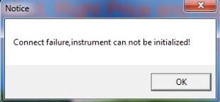
図4-2
[OK]をクリックしてソフトウェアの初期インターフェースを開き、図4-3に示すように[テスト] > [ポート設定]をクリックします。
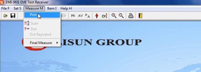
図4-3
Simply select the correct communication port number manually, as shown in Figure 4-4.
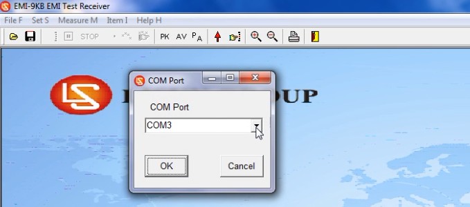
図4-4
As shown in Figures 4 and 5, you can go to “My Computer” > “Properties” > “Device Manager” to verify the communication port used by the device.
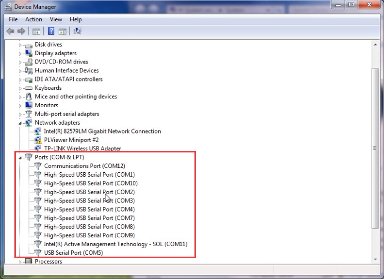
図4~5
The next time you open the software, it will open directly to the initial interface. Note: If the communication port changes, you will need to reselect the correct communication port.
4.2 Introduction to Software Interface Features
4.2.1 ファイルメニュー
4.2.1.1 ドロップダウンリスト
図4~6を参照。
| 数 | お願い |
| ① | Open the EMC file |
| ② | テスト結果をemcファイルとして保存します。注:emcファイルは、以下の方法でのみ開くことができます。 LISUN EMI-9KB ソフトウェアを使用して、WindowsXNUMX XNUMXビット上で動作する XNUMXTB RAID XNUMX を備えたデスクトップ コンピューターで録画されます。 |
| ③ | テストレポート設定 |
| ④ | Print a report that includes data from the final test points |
| ⑤ | Print a report that includes data on points of interest |
| ⑥ | ソフトウェアを終了する |
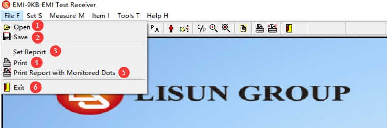
図4~6
4.2.1.2 Report Option Information
テストレポートを保存または印刷する際には、図4-7に示すように、まず次の画面が表示されます。
| 数 | お願い |
| ① | 最終検査ポイント/重点検査ポイントのデータを保存/印刷しますか? |
| ② | Fill in the test-related information |
| ③ | Fill in the Laboratory Information |
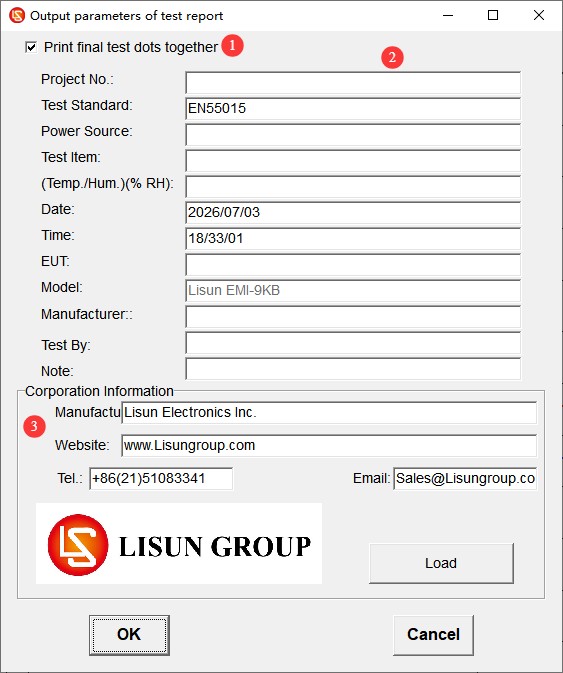
図4-7
4.2.2 設定メニュー
4.2.2.1 ドロップダウンリスト
図4~8を参照。
| 数 | お願い |
| ① | Test Standards: Select, Add, Edit, or Delete Standards |
| ② | テストパラメータ:変更は不要です。デフォルト設定をそのまま使用してください。 |
| ③ | System Calibration: Used by professional engineers when commissioning the equipment; this function is not required during normal operation. |
| ④ | 減衰器:実際の状況に基づいて選択してください。 |
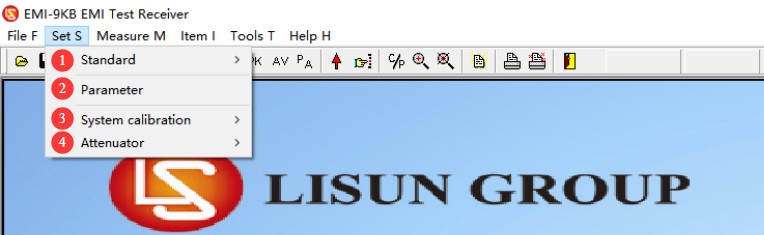
図4-8
4.2.2.2 テスト標準オプション
図4~9を参照。
| 数 | お願い |
| ① | 選択基準:以前に追加された基準のみを選択できます。基準のパラメータを変更することはできません。 |
| ② | Add, modify, or delete standards. Note: Please proceed with caution; all standards and limit curves are added according to the standards. If you have other standard data not included in our software, please send us the relevant standards, and we will add them for you. |
| ③ | Absorbing Clamps, Voltage Probes, CDN network correction. Note: For use only by LISUN professional engineers when debugging software. |
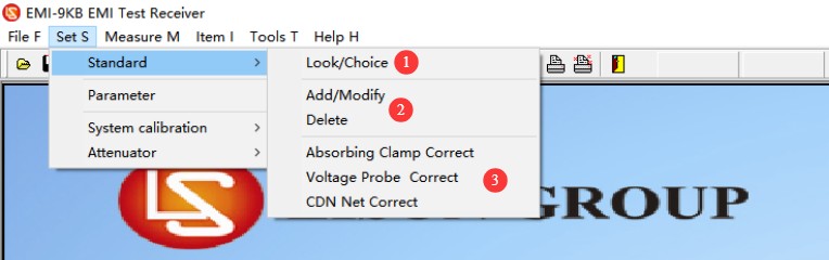
図4-9
4.2.2.3 アッテネータのオプション
図4-10を参照してください。
| 数 | お願い |
| ① | 減衰器を使用しないでください |
| ② | 減衰器を使用する場合は、ソフトウェア上で適切な減衰パラメータを選択して入力してください。 |
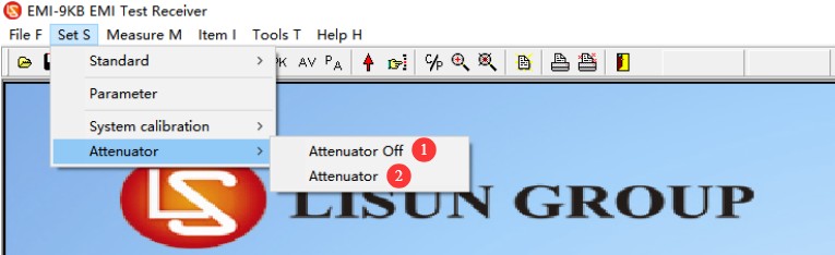
図4-10
Note: When connecting the EMI-9KB から AB-CLP, a 6 dB attenuator must also be connected; please set the correct attenuator parameters before use.
4.2.3 テストメニュー
図4-11を参照してください。
| 数 | お願い |
| ① | For communication port settings, see 4.1.3 |
| ② | スキャン:その時点で選択された基準とパラメータ設定に従ってスキャンテストを実行します。 |
| ③ | スポットテスト:特定の周波数ポイントのデータのみを表示したい場合は、ここをクリックして周波数を手動で入力し、テストを実行してください。 |
| ④ | 最終テスト:スキャンテストが完了した後、特定のポイントの特定のデータを再度テストしたい場合は、最終テストを実行できます。 |
| ⑤ | 自動最終テスト:ソフトウェアは、テスト結果に基づいて最終テスト用の代表的な周波数ポイントを自動的に選択します。 |
| ⑥ | Manual Final Test: Users manually add the frequency points to be tested based on their needs. |
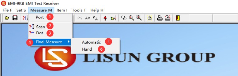
図4-11
4.2.4 ディスプレイメニュー
図4-12を参照してください。
| 数 | お願い |
| ① | このグラフは、デフォルトのPK線とAV線の両方を示しています。 |
| ② | Add a monitoring point; this feature works the same as in the final test in version 4.2.3, and you can manually set the frequency points. |
| ③ | 限界曲線外のデータを表示する |
| ④ | Display the data for the final test point |
| ⑤ | After performing two consecutive scan tests, you can click to compare the results of the two tests. |
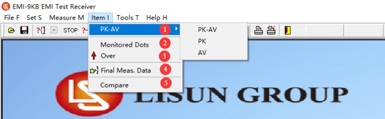
図4-12
4.2.5 Introduction to Navigation Bar Shortcut Keys
図4-13を参照してください。
| 数 | お願い |
| ① | Open the EMC file |
| ② | emcファイルとして保存 |
| ③ | スキャンテスト |
| ④ | Pause Testing |
| ⑤ | テストを停止する |
| ⑥ | Spot Measurement |
| ⑦ | 自動最終テスト |
| ⑧ | 手動最終テスト |
| ⑨ | 表示曲線:PK、AV、PK+AV |
| ⑩ | 限界曲線外のデータを表示する |
| ⑪ | 最終チェックポイントのデータを表示します |
| ⑫ | Show or hide overlapping data points (hiding overlapping data points makes the curve clearer) |
| ⑬ | Zoom In/Out: You can zoom in on the curve for easier viewing. After clicking, scroll the middle mouse button wheel in the curve display area to zoom in or out. |
| ⑭ | テストレポート設定 |
| ⑮ | 最終テストポイントデータを含むレポートを印刷する |
| ⑯ | Print a report that includes data on points of interest |
| ⑰ | ソフトウェアを終了する |
| ⑱ | デバイスの内部モジュールのパラメータを表示します。デバッグ時に専門のエンジニアのみが使用することを目的としています。 |
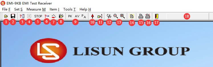
図4-13
5. Pre-Test Preparation and System Setup
5.1 Test Environment Requirements
Shielded Room Solution (Compliance Testing): Formal conformity assessment testing must be conducted in a standard-compliant electromagnetic shielded room that completely isolates the test equipment from external interference, ensuring the authority of the test results.
Standard Room Specifications (Preliminary Testing): For R& D preliminary testing, a dedicated room with an area of at least 15 square meters and free of other devices that generate strong electromagnetic interference should be used. Priority should be given to rooms on the first floor to facilitate grounding and reduce grounding resistance.
Sufficient space must be reserved in the test area to accommodate the length of the slide rails and the required spacing between equipment.
5.2 Requirements for Standard Test Setups
The test setup strictly complies with the requirements of the CISPR 16-2-2 / GB/T 6113.202 standard and is divided into two configurations—desktop and floor-standing—based on the type of equipment under test.
5.2.1 Layout of Benchtop Equipment Under Test (EUT)
See Figure 5-1 (taken from CISPR 16-2-2, Figure 8).
Place the insulation test bench above the ground reference plane, with the bench top at a height of 0.8 m; place the equipment under test securely on the test bench, with the rear of the equipment 0.4 m away from the metal wall or ground reference plane.
Place an insulated slide rail that is 0.8 m high horizontally; the rail must be at least 6 m long and located on the same horizontal plane as the equipment under test.
The lead under test (LUT) must be straightened and placed horizontally, with one end connected to the device under test and the other end extending along the slide rail and hanging naturally to the ground, where it is connected to a power source; The total length of the lead under test shall be no less than 7.5 m (including a 6 m section on the slide rail, a 1 m hanging section, and a 0.5 m allowance). If the length of the equipment’s original power cord is insufficient, it must be extended using a replacement cord of the same type and construction.
Open the Absorbing Clamp, insert the wire to be tested into the center hole of the Clamp, close the Clamp, and secure the latch; place the Absorbing Clamp on the slide rail so that it can slide freely along the rail.
The initial distance between the slide rail reference point (SRP) and the clamp reference point (CRP) is set to 10 ± 1 cm. This distance has a significant impact on the test results and must be strictly controlled.
Connect an attenuator, coaxial cable, and the EMI-9KB receiver to the output of the absorption clamp as specified in Chapter 3. Place the receiver on the outer side of the end of the slide rail to avoid interfering with the test area.
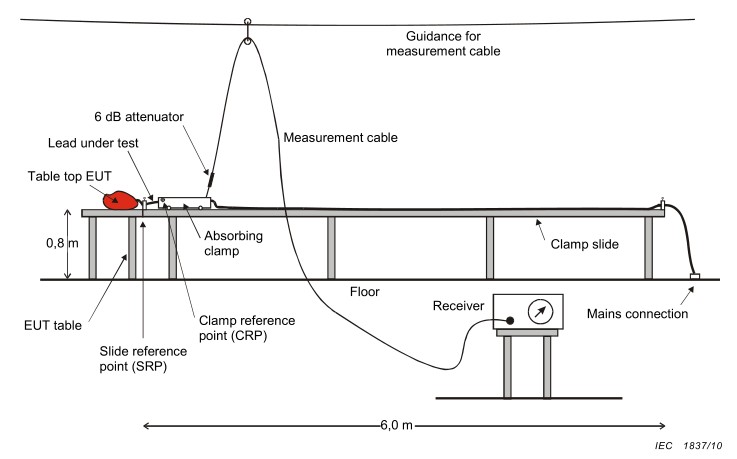
図5-1
5.2.2 Floor-Standing Equipment Under Test (EUT) Setup
See Figure 5-2 (taken from CISPR 16-2-2, Figure 9).
Place a metal grounding reference plate measuring at least 2 m × 2 m on the floor. Place an insulating mat 0.1 m high on top of the metal plate, and carefully place the device under test on the insulating mat.
The insulated rail remains at a height of 0.8 m and is positioned horizontally next to the equipment under test; the rest of the wiring layout, absorption clamp installation, and spacing requirements are the same as those for the benchtop unit.
All surfaces of the device under test must be at least 50 cm from the edge of any metal plate and at least 80 cm from any conductive objects in the vicinity.
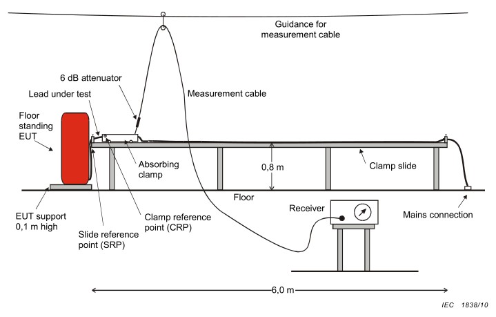
図5-2
6. Procedure for Interference Power Testing
6.1 Powering On and Warm-Up
First, turn on the Isolation Transformer, then turn on the EMI-9KB receiver, and finally turn on the computer and launch the test software;
After turning on the receiver, let it warm up for 10 minutes; wait until the internal circuitry has stabilized before beginning the test;
Turn on the power to the device under test to bring it into normal operating mode, and allow it to warm up to a stable operating state in accordance with the standard requirements (typically 15 to 30 minutes).
6.2 試験パラメータの確認
6.2.1 Selection of Standards
Refer to Section 4.2.2.2. Go to the standard selection menu and choose the standard labeled “Power”; this is the standard for Absorbing Clamps. See Figure 6-1.
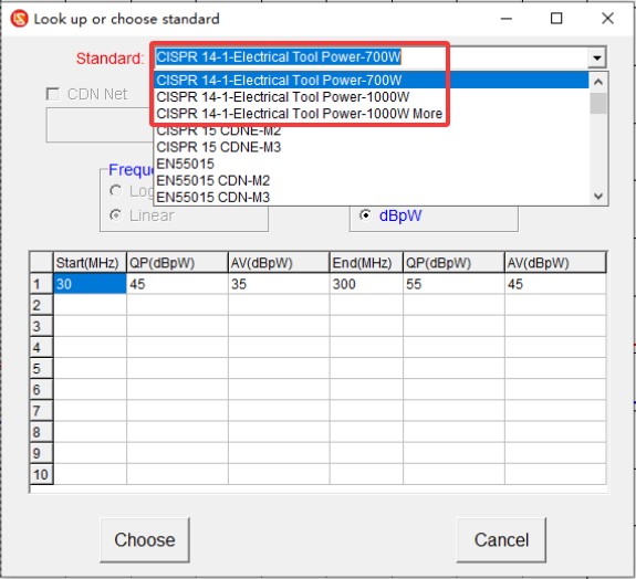
図6-1
6.2.2 Attenuator Settings
Refer to Section 4.2.2.3 and select a 6 dB attenuator, as shown in Figure 6-2.
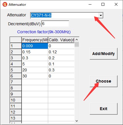
図6-2
6.4 スキャンテスト
Click “Scan Test,” wait for the scan to complete, and if any issues arise, click “Stop Test,” make the necessary adjustments, and then restart the test. The scan is complete; see Figure 6-3.
Red line: Quasi-peak (QP) limit line;
Blue line: Average (AV) limit line;
Green curve: Peak (PK) test curve;
青色の曲線:平均(AV)テスト曲線。
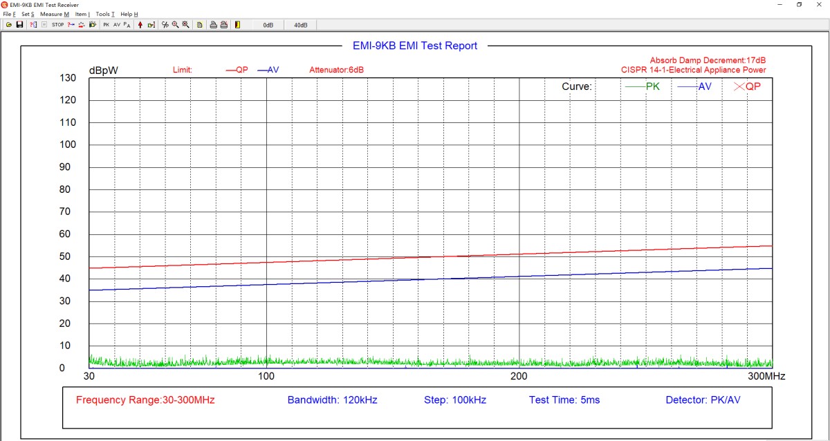
図6-3
6.5最終試験
If the average values (AV) of the test results are all below the limit curve, and the peak values (PK) are all below the quasi-peak (QP) limit curve, then the EUT meets the standard requirements, because the actual quasi-peak (QP) value measured during testing will not exceed the peak (PK) value. If the tested peak value (PK) exceeds the quasi-peak (QP) limit curve, the EUT does not necessarily fail to meet the standard requirements; a final test must be conducted.
6.5.1 自動最終テスト
テストする周波数ポイントの数を入力すると、図6-4に示すように、ソフトウェアがテスト曲線に基づいて周波数ポイントを自動的に選択し、最終テストを実行します。
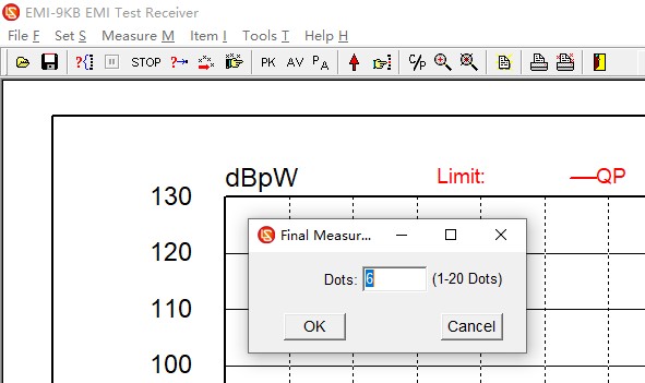
図6-4
6.5.2 手動による最終テスト
In the software test curve area, right-click on the point where you want to perform the final test, as shown in Figure 6-5.
| 数 | お願い |
| ① | Add Endpoint |
| ② | エンドポイントの削除 |
| ③ | 必要な最終テストポイントをすべて入力したら、「最終テストを開始」をクリックしてください。 |
| ④ | If you no longer wish to participate in the final test, click “Cancel Final Test.” |
| ⑤ | 青いひし形は、追加された最終テストポイントの位置を示しています。 |
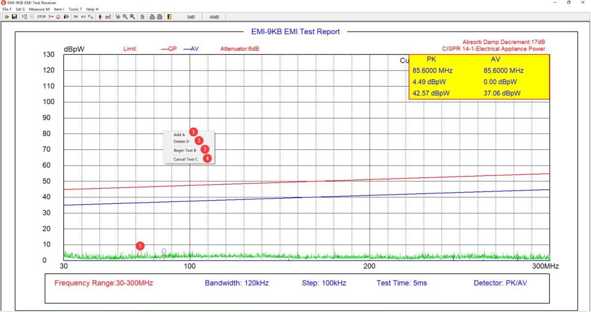
図6-5
6.5.3 興味のある地点の追加
図6-6を参照してください。
| 数 | お願い |
| ① | クリックすると、現在の画面からすべての周波数ポイントとデータがクリアされます。 |
| ② | Tap to edit the frequency point status; tap again to exit the frequency point editing mode. |
| ③ | 編集用の周波数ポイント。各周波数ポイントを手動で入力できます。 |
| ④ | 先ほど編集した周波数ポイントファイルを直接読み込むことができます。 |
| ⑤ | You can save the frequency point data file you are currently editing so that it can be directly accessed during the final test. |
| ⑥ | 「データの作成」をクリックすると、現在のテストレポートから対応する周波数ポイントのテストデータを直接読み込むことができます。 |
| ⑦ | 現在のテストレポートから、対応する周波数ポイントのテストデータを読み取ってください。 |
| ⑧ | Click “Clear Data” to clear the retrieved data. |
| ⑨ | Click OK to save the current focus point data to the test report. |
| ⑩ | Click EXIT to exit immediately without saving the current screen’s focus point data. |
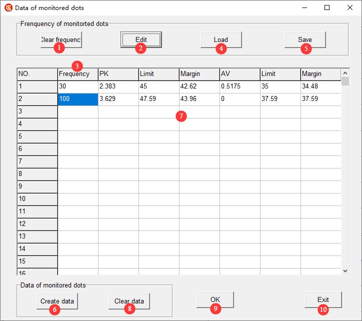
図6-6
6.5.4 Interpretation of Final Test Data
See Figures 6–7. The red X marks the quasi-peak (QP) values from the final test. If all quasi-peak (QP) values from the final test are below the quasi-peak (QP) limit curve, the EUT meets the standard requirements. Otherwise, it does not meet the standard requirements.
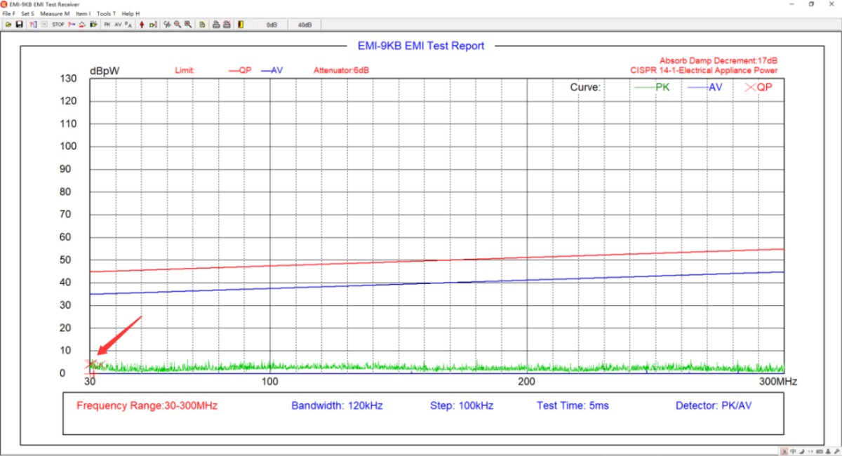
図6~7
6.6 Save and Print the Test Report
テストレポートの保存または印刷については、セクション4.2.1を参照してください。
6.7 Procedure for Shutting Down the Machine at the End of a Test
Ensure the equipment is in the “test stop” state → Disconnect the coaxial cable on the EMI-9KB receiver side → Turn off the EUT’s power → Turn off the receiver and the computer → Turn off the Isolation Transformer.
7. 機器の日常的なメンテナンスと手入れ
7.1。XNUMX日常のメンテナンス
7.1.1 Absorbing Clamps
After each use, wipe the surface of the pliers with a dry, soft cloth to remove dust and stains; Do not use highly corrosive solvents such as gasoline, acetone, or thinners for cleaning. To remove stubborn stains, use a lint-free cloth dipped in a small amount of anhydrous ethanol to wipe the area quickly, then dry it immediately.
Check the latch and hinge of the pliers monthly to ensure they open and close smoothly; you may apply a small amount of silicone grease for lubrication. Inspect the N-type output connector, remove any oxidation, and cover it with a protective cap when not in use to prevent dust from entering.
Handle the equipment with care; do not drop or subject it to impact, to prevent the internal ferrite cores from shattering. Do not use the pliers to grip hard objects or apply excessive force when opening or closing them.
Do not disassemble the clamp body on your own. The internal magnetic ring and structural alignment have been calibrated before shipment; disassembly will result in a loss of testing accuracy.
7.1.2 Coaxial Cables and Attenuators
Avoid bending coaxial cables sharply, stepping on them, or subjecting them to pressure from heavy objects. When storing them, coil them loosely to prevent the internal conductors from breaking.
減衰器やコネクタなどの精密な付属品は、落下による内部損傷を防ぐため、慎重に取り扱ってください。
7.2 Storage Specifications
7.2.1 保管環境の要件
温度:5℃~35℃、相対湿度:65%RH以下、乾燥した、埃のない、腐食性ガスのない環境。
7.2.2 長期保管業務
Turn off the power and unplug all cables; clean the equipment and wrap it in dust-proof film.
7.3 校正間隔の要件
機器の測定精度と動作信頼性を確保するため、定期的に認定された第三者計測機関に送付して校正を受けることを推奨します。推奨される校正間隔は12ヶ月です。具体的な校正間隔は、使用頻度、環境条件、および品質システム要件に基づいてユーザーが決定できます。
8.よくある問題のトラブルシューティングと解決
8.1 Absorbing Clamps
| 障害症状 | 手順 |
| The suction forceps do not open and close smoothly, and the latch does not secure tightly | Clean the pivot shaft and apply a small amount of silicone grease for lubrication; remove any foreign objects from inside the jaws and ensure the magnetic ring is undamaged; verify that the diameter of the cable being tested is ≤20 mm, and replace it with a suitable cable. |
8.2 EMI-9KB 受信機
| 障害症状 | 手順 |
| Various error messages appear while using the software, such as “The software cannot be opened” or “An error occurred during scanning.” | 管理者アカウントでコンピュータにログインしていることを確認し、ソフトウェアが管理者権限で実行されていることを確認してください。 |
| The software worked normally during the scan test, but crashed during the final test. | The final test has stricter communication requirements than the scan test. Please ensure that you are using only our original communication cable and no other communication cables or extension cords; please ensure that you are using the communication port on the back of the desktop computer (USB ports on laptops and those on the front of desktop computers typically do not provide sufficient power, which can affect communication); if that still does not work, please try adding an RS232 port to your computer and use only an RS232 cable for communication—do not use an RS232-to-USB adapter. |
| Test results are generally lower or higher than expected | ソフトウェア減衰器の設定が実際の状況と一致していることを確認してください。 |
| 試験結果は常にバックグラウンドノイズに近く、EMI受信機は信号を検出できません。 | 同軸ケーブルの接続を確認し、必要に応じてケーブルを交換して再度試してください。 |
| Excessively high background noise and significant fluctuations in test data | Verify that all equipment in the system uses Isolation Transformers; optimize the grounding system to reduce ground resistance; turn off other electrical equipment in the laboratory or conduct testing inside a shielded room. |