
 英語
英語 中文简体
中文简体 Русский
 Español
 Português
 Türkçe
 العربية
 Deutsch
 Polski
 Italiano
 Français
 한국어
한국어 ไทย
ไทย Tiếng Việt
 日本語
日本語





























ベンチトップ分光光度計
ユーザーズマニュアル
適用 LISUN models: DSCD-950P
1. Basic Understanding of Equipment
1.1 Key Parameters
| 技術パラメータ | お願い |
|---|---|
| Lighting/Light-Receiving System | Reflectance: d/8 (diffuse illumination, 8° reception angle); Transmittance: d/0 (diffuse illumination, vertical reception angle); SCI (including specular reflection) and SCE (excluding specular reflection) are measured simultaneously. Complies with standards: CIE No. 15, GB/T 3978, GB 2893, GB/T 18833, ISO 7724-1, DIN 5033 Part 7, JIS Z8722 Condition C, ASTM E1164, ASTM-D1003-07 |
| センサー | シリコンフォトダイオードアレイ |
| Method of Spectral Separation | 凹面格子 |
| 積分球直径 | 20 mm |
| 測定波長範囲 | 360 nm~780 nm |
| Measuring Wavelength Intervals | 10 nmの |
| Half-wave width | 5 nmの |
| 反射率測定範囲 | 0–200%, resolution 0.01% |
| 照明源 | Pulsed Xenon Lamps and LEDs |
| Ultraviolet Measurement | Includes UV, 400 nm cut-off, 420 nm cut-off, and 460 nm cut-off |
| 測定時間 | SCI or SCE mode: <2 seconds; simultaneous SCI+SCE measurement: <4 seconds |
| Illumination/Measurement Aperture | Reflection: Φ30 mm, Φ18mm, Φ11mm, Φ6 mm; users できる customize the aperture size, and the system automatically detects aperture changes. Transmission :Φ25mm |
| Transmission Measurement Specifications | Sample width and height: No restrictions; thickness: ≤50 mm |
| 再現性 | XLAV Spectral Reflectance/Transmittance: Standard deviation within 0.1% XLAV Colorimetric Values: Standard deviation ΔE*ab within 0.015 (after instrument calibration, 30 measurements of a white calibration plate taken at 10-second intervals) |
| Difference between platforms | XLAV ΔE*ab 0.15 (based on the average value measured on the BCRA Series 12 color chart at 23°C) |
| Standard Observer | 2° standard observer and 10° standard observer |
| Observing the Light Source | A、C、D50、D55、D65、D75、F1、F2、F3、F4、F5、F6、F7、F8、F9、F10、F11、F12、CWF、U30、DLF、NBF、TL83、TL84 |
| 言語 | Simplified Chinese, English, Traditional Chinese, Russian, Spanish, Portuguese, Japanese, Thai, Korean, German, French, Polish, Indonesian |
| 表示内容 | Spectral data, spectral graphs, chromaticity data, color difference data, color difference graphs, pass/fail determination, simulated colors, color evaluation, haze, liquid color, color bias |
| カラースペース | L*a*b、L*C*h、ハンターラボ、Yxy、XYZ |
| Chromaticity Parameters | WI (ASTM E313-00, ASTM E313-73, CIE/ISO, AATCC, Hunter, Taube, Berger Stensby), YI (ASTM D1925, ASTM E313-00, ASTM E313-73), Tint (ASTM E313-00), Metamerism Index (Milm), Color Fastness to Rubbing, Color Fastness to Light, ISO Brightness, R457, A Density, T Density, E Density, M Density, APHA/Hazen/Pt-Co (Platinum-Cobalt Index), Gardner (Gardner Index), Saybolt (Saybolt Index), ASTM Color, Haze, Total Transmittance, Hiding Power, Consistency, Strength |
| 色差式 | ΔE*ab, ΔE*CH, ΔE*uv, ΔE*cmc, ΔE*94, ΔE*00, ΔEab (Hunter), 555 hue classification |
| 収納スペース | 8GB |
| 画面サイズ | 7インチの静電容量式タッチスクリーン |
| オペレーティングシステム | Android |
| 電源 | 12V / 3A |
| 動作温度および湿度 | 5–40°C, relative humidity 80% or less (at 35°C), with no condensation |
| 保管温度と湿度 | -20 to 45°C, relative humidity of 80% or less (at 35°C), with no condensation |
| 添付ファイル | Power adapter, data cable, transmission fixture, black chamber, white plate, green plate, 30 mm aperture plate, 18 mm aperture plate, 11 mm aperture plate, 6 mm aperture plate, cuvette |
| オプションのアクセサリ | Heated transmission fixture (including control circuit), vertical stand, pneumatic push rods (including control circuitry), small sample clamping accessories, reflectance cuvette holder, corrosion-resistant protective plate (non-removable), fiber test kit, film fixture, micro-transmission fixture, rolling case, European-standard plug, U. S.-standard plug |
| インタフェース | RS232, USB-A, USB-B |
| 出来高 | Length, Width, Height: 465 × 240 × 260 mm |
| 重量 | 10.8キロ |
| その他 | 1. Camera framing and positioning 2. The instrument can measure from the side, upward, or downward (using accessories) 3 . Automatic temperature and humidity compensation |
1.2 Unboxing and Checking the Accessories
1.2.1開梱
When unpacking the device, handle it gently to avoid scratching the outer casing with sharp tools. After unpacking, first inspect the exterior of the device to ensure there is no visible deformation or dents, and that the buttons are not damaged or loose. If you notice any abnormalities with the device or its accessories, please contact us immediately.
1.2.2 Downloading Electronic Documents
Download links for the electronic user manual, software, calibration certificate, warranty card, and other materials have been sent via email. Please download them as soon as possible. If you missed the email, please feel free to contact us to request the download links again.
2.使用上の注意
2.1 Precautions Before Operation
2.1.1 環境の準備
Before taking a measurement, allow the device and the sample to rest in the same environment for at least 30 minutes to ensure that their temperatures are the same. The measurement environment must be free from direct strong light and stray light interference; avoid operating the device in environments with high temperatures, high humidity, or excessive dust.
2.1.2 サンプルの準備
The surface of the sample being tested must be flat, clean, free of stains, and free of scratches. If the sample is a powder or liquid, it must be placed in a dedicated cuvette to ensure that the sample surface completely covers the measurement aperture without any gaps; Select an appropriate measurement aperture based on the shape of the sample. Ensure that the measurement end fits snugly against the sample’s measurement area to prevent light leakage.
2.2 使用上の注意
2.2.1 Functional Operation Specifications
Do not force a shutdown or disconnect the USB cable during the device’s self-test, calibration, or measurement processes. When switching measurement parameters, wait until the display has finished loading before proceeding to the next step. If you need to export saved measurement data, ensure the connection is established before shutting down the device to prevent data loss.
2.2.2 Contraindications for Equipment Use
Do not touch the optical components inside the measurement port with your bare hands, and do not point the measurement end toward a strong light source; do not drop, bump, or crush the device, and avoid exposing the body to water or other liquids.
2.3 安全上の警告
Do not attempt to disassemble or replace any internal parts of the device. In the event of a malfunction, contact official customer service or an authorized dealer for assistance. Unauthorized disassembly will void the warranty;
If any liquids, dust, or other substances enter the device, immediately turn off the power, disconnect the charging cable, and contact customer service right away. Do not continue to use the device.
2.4 その他
For matters not covered in this manual, please proceed with caution or contact us.
3. Hardware Operations
3.1 Main Unit and Accessories
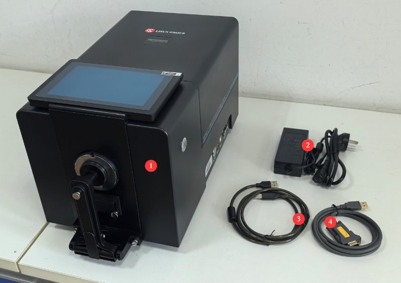
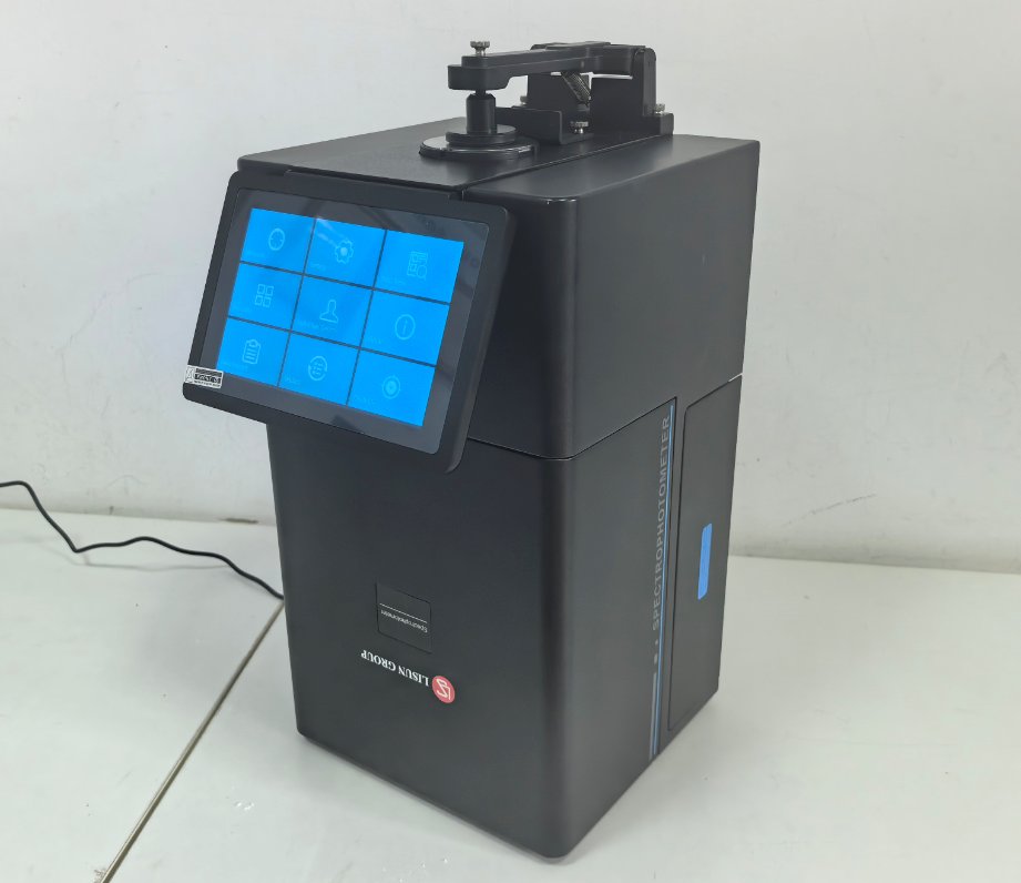
After unboxing, you will find the main unit and accessories shown in Figure 3-1.
| 数 | お願い |
|---|---|
| ① | DSCD-950P Main Unit |
| ② | 電源アダプタ |
| ③ | USB cable; if you need to use the software on your computer, you must connect the device to the computer. |
| ④ | RS232-to-USB adapter cable; functions the same as a USB cable; for backup use |
3.2 Introduction to the Host System Architecture
3.2.1 正面図
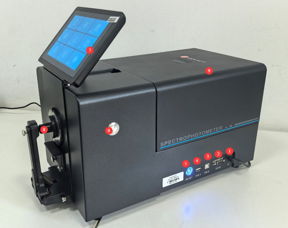
図3-2を参照してください。
| 数 | お願い |
|---|---|
| ① | 電源アダプタの接続 |
| ② | RS-232 interface, spare |
| ③ | USB B port: When you need to use the software on your computer, connect the device to your computer using the included USB cable. |
| ④ | USB-A port for connecting a USB flash drive to export test reports |
| ⑤ | 電源スイッチ |
| ⑥ | Measurement button: Press to run the test; this functions the same as the measurement button on the touchscreen. |
| ⑦ | Touchscreen, adjustable angle |
| ⑧ | Reflection Measurement Component; see Section 3.3.1 for details |
| ⑨ | Transmission Measurement Enclosure |
3.2.2 背面図
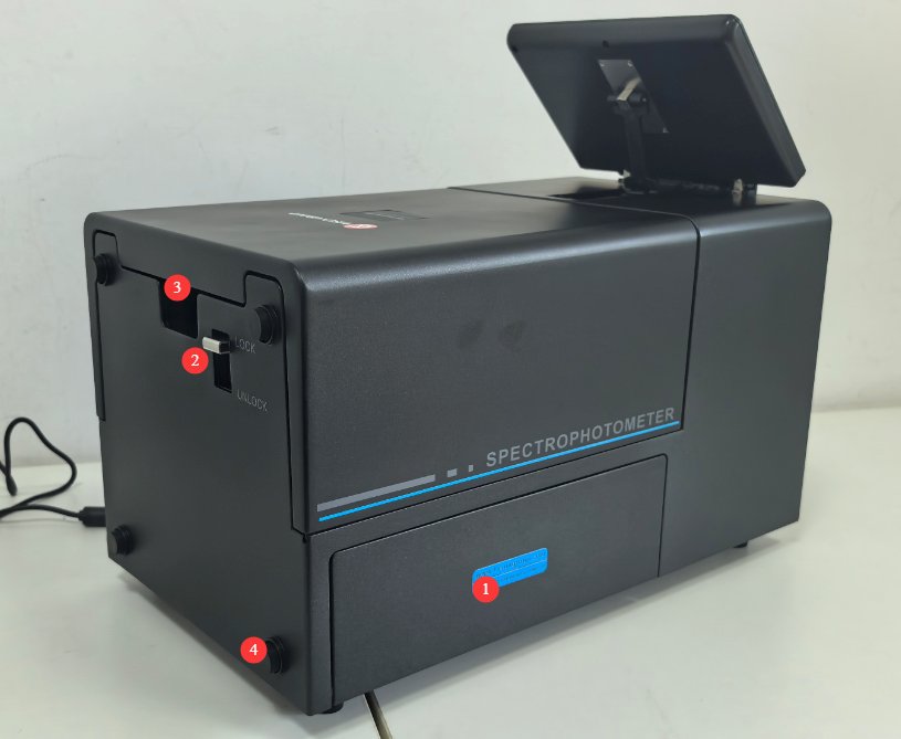
図3-3を参照してください。
| 数 | お願い |
|---|---|
| ① | Accessory drawer; press to open. See Section 3.2.3 for details. Note: Accessories inside the drawer may become loose during shipping, preventing the drawer from pulling out properly. Do not use excessive force to pull it out. |
| ② | The housing lock mechanism prevents the housing from moving when locked; when unlocked, the housing can be pulled open horizontally to use the transmission measurement assembly. For details, see Section 3.3.2. |
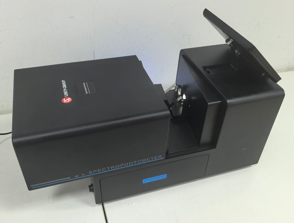
| ③ | When using the transmission measurement assembly, unlock the housing lock and pull the housing horizontally away from this point, as shown in Figure 3-4. |
| ④ | If you are not using the transmission measurement module, you can stand the instrument upright to make it easier to use the reflection measurement module; see Figure 3-5. |
3.2.3 Introduction to Accessories in the Accessories Drawer
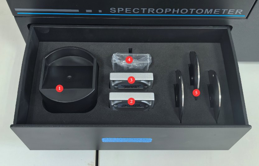
See Figures 3–6.
| 数 | お願い |
|---|---|
| ① | Black cavity; use during calibration |
| ② | Whiteboard, used for calibration |
| ③ | Green board, used for calibration |
| ④ | Cuvette, used to hold liquid or powdered samples |
| ⑤ | The reflectance measurement kit includes interchangeable measurement apertures, with a total of four sizes: 6 mm, 11 mm, 18 mm, and 30 mm. One of these is already installed on the instrument, and the other three are stored in the accessory drawer. |
3.3 Introduction to the Measurement Components
3.3.1 Reflectance Measurement Components
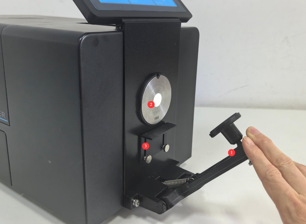
図3-7を参照してください。
| 数 | お願い |
|---|---|
| ① | Damped spring mount; when pulled out, it allows for easy installation of calibration plates or samples |
| ② | The measuring aperture is magnetically attached and can be replaced with other sizes depending on the sample size; when taking measurements, ensure that the sample completely covers the measuring aperture. |
| ③ | Sample holder, height-adjustable |
When using the device for the first time, you must calibrate it before taking measurements. The default calibration validity period is 8 hours; that is, recalibration is required after 8 hours have elapsed. Even if 8 hours have not yet passed, you must recalibrate the device as prompted if measurement conditions change—for example, if the measurement orifice is replaced. See Section 4.5.1 for calibration instructions.
3.3.2 Transmission Measurement Assembly
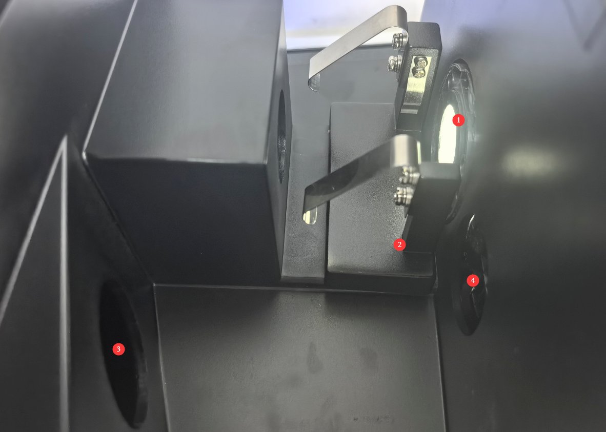
See Figures 3–8.
| 数 | お願い |
|---|---|
| ① | The transmission measurement aperture is 25 mm; other apertures must be purchased separately. Note: The sample must completely cover the measurement aperture. |
| ② | Magnetic sample holder; if not needed, it can be removed |
| ③④ | For reflection measurements, the optical path used for transmission measurements does not need to be obstructed. |
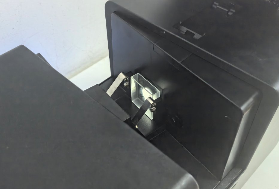
When using a cuvette, install it as shown in Figure 3-9.
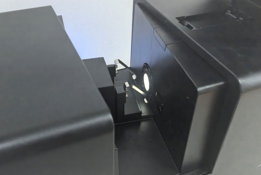
When using the spring clip, you can invert the magnetic sample holder and use the spring clip to secure the sample within the measurement aperture, as shown in Figure 3-10.
If the housing cannot be closed after installing a large sample, testing can still proceed normally; however, the calibration procedure must be performed under the same conditions as the test (i.e., the housing must remain open during the calibration phase as well).
When using the device for the first time, you must calibrate it before taking measurements. The default calibration validity period is 8 hours; that is, recalibration is required after 8 hours have elapsed. Even if 8 hours have not yet passed, you must recalibrate the device as prompted or on your own initiative if you notice a change in measurement conditions. See Section 4.5.2 for calibration instructions.
4. Touchscreen Program Operation
4.1 Getting Started and Introduction to the Setup Wizard
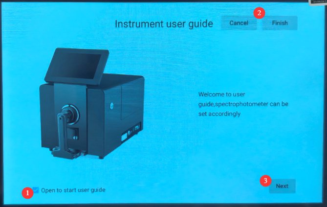
After turning on the device, the navigation screen will appear. Follow the on-screen prompts to configure the settings as needed. See Figure 4-1.
| 数 | お願い |
|---|---|
| ① | Run the Setup Wizard at Startup? |
| ② | Cancel or Exit the Wizard |
| ③ | Click “Next” to proceed to the mode selection screen, as shown in Figure 4-2. |
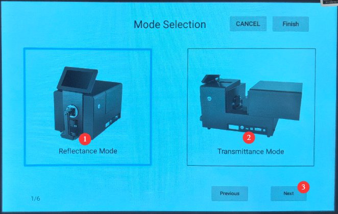
| 数 | お願い |
|---|---|
| ① | For opaque samples, the reflectance measurement mode must be used. |
| ② | For transparent samples, use the transmission measurement mode. |
| ③ | Click “Next” to proceed to the instrument settings screen, as shown in Figure 4-3. |
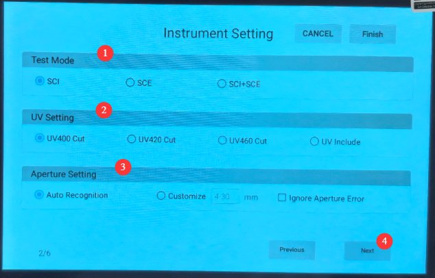
| 数 | お願い |
|---|---|
| ① | Test Mode Selection: SCI (including specular reflection), SCE (excluding specular reflection), or simultaneous SCI+SCE measurement |
| ② | UV settings: UV cut-off at 400 nm, UV cut-off at 420 nm, UV cut-off at 460 nm, or UV included |
| ③ | To set the aperture for the reflectance measurement module, simply select “Auto-detect.” |
| ④ | Click “Next” to proceed to the parameter settings screen, as shown in Figure 4-4. |
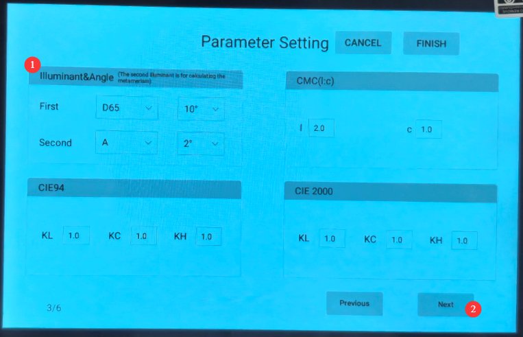
-
- 
| 数 | お願い |
|---|---|
| ① | Light Source and Viewing Angle Settings: You can configure the light source and angle for calculated data. The first light source and angle apply to calculated data in all modes, while the second light source is used only for metamerism calculations (Note: The light source and angle for “Similar Color Search” and “My Colors” are fixed at D65/10°). |
| ② | Click “Next” to proceed to the tolerance settings screen, as shown in Figures 4-5. |
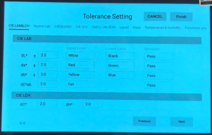
The tolerance settings screen is used to determine whether a sample’s measurement results pass or fail. CIE LAB users can customize the prompt messages here. Click “Next” to proceed to the other settings screen, as shown in Figures 4–6.
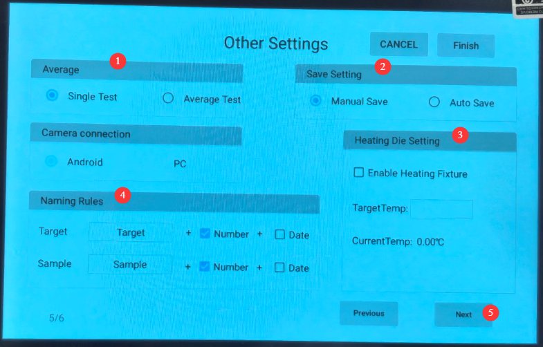
| 数 | お願い |
|---|---|
| ① | Default setting; the factory default is single measurement. |
| ② | Save settings; the factory default is to save manually. |
| ③ | Heating Fixture Settings—This feature is available when a heating fixture is selected. |
| ④ | Naming Convention Settings |
| ⑤ | Click “Next” to proceed to the template selection screen, as shown in Figure 4-7. |
| 数 | お願い |
|---|---|
| ① | Select the parameters to measure and display |
| ② | Test Results: Preview of Results |
| ③ | Click to complete the wizard |
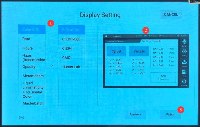
Introduction to Measurement and Display Parameters:
| 技術パラメータ | お願い |
|---|---|
| 色差 | CIELABCH, CIEDE2000, CIE94, CMC, HunterLab |
| Rescale データ | This mode displays all parameters that the instrument can measure, except for haze and opacity. |
| 画像 | CIE LAB charts, Yxy charts, Luv charts, reflectance/transmittance charts, K/S curves, absorbance curves |
| カバレッジ | Measuring Opacity Parameters |
| Chromatic Anomaly | Measuring Metamerism Parameters |
| 液体の色 | Measurement of Saybolt, ASTM color, platinum-cobalt color, and Gardner color |
| Search for Similar Colors | Find the color in my color database that most closely matches the current measurement data |
| カラーマスターバッチ | Designed specifically for color measurement of color masterbatches |
| 二酸化チタン | Designed specifically for measuring the color of titanium dioxide |
| paste | Designed specifically for measuring the color of pastes |
Note: The measurement steps may vary depending on the parameter being measured. Please follow the on-screen prompts.
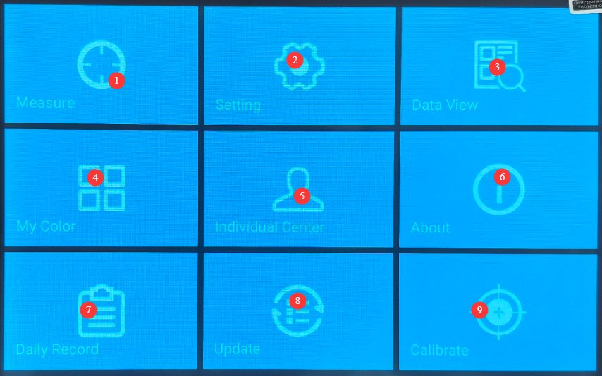
4.2 Introduction to the Main Menu
See Figures 4–8.
| 数 | お願い |
|---|---|
| ① | Measurement Interface; see Section 4.3 for details |
| ② | Settings interface; see Section 4.4 for details |
| ③ | Data Viewer interface, used to view and process saved measurement data |
| ④ | My Colors: View saved colors or connect to the internet to view colors in the cloud |
| ⑤ | My Account, for changing your login password |
| ⑥ | About, Display Product Information |
| ⑦ | Instrument Log |
| ⑧ | Update: Firmware upgrade channel for the instrument’s touchscreen; the software update package is provided by us. |
| ⑨ | Calibration; Perform calibration proactively. For details, see Section 4.5. |
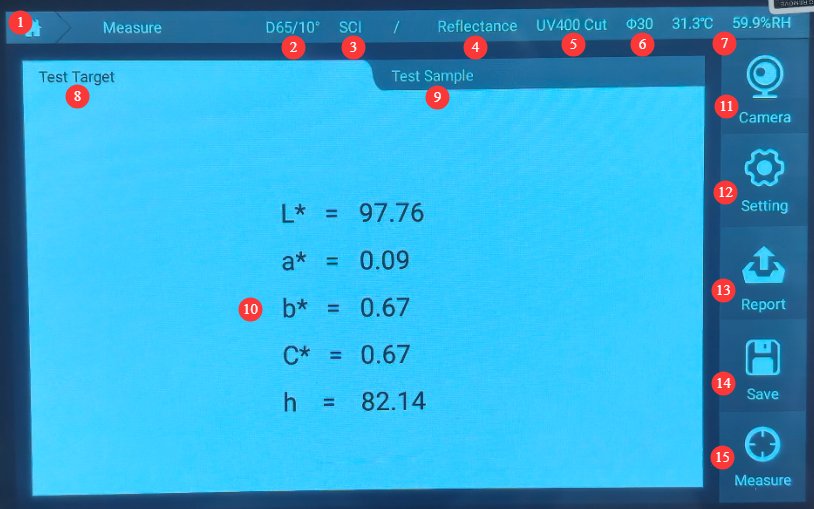
4.3 Introduction to the Measurement Interface
Take the CIELAB color difference measurement interface as an example; see Figure 4-9.
| 数 | お願い |
|---|---|
| ① | Click to return to the main menu |
| ② | Light Source, Angle |
| ③ | SCI/SCE Status |
| ④ | Reflection/Transmission Mode |
| ⑤ | UV Status |
| ⑥ | Reflection Measurement Aperture |
| ⑦ | 周囲温度と湿度 |
| ⑧ | Reference Sample Measurement Interface |
| ⑨ | Sample Measurement Interface |
| ⑩ | The measurement results show that |
| ⑪ | Camera: Click to view the measurement aperture of the reflectance measurement component and the actual condition of the sample. |
| ⑫ | Settings screen: This screen functions the same as the Settings screen in the 4.2 Main Menu; see 4.4 for a detailed description. |
| ⑬ | Insert the USB flash drive into the instrument’s USB A port, and you can click to export the test report directly to the USB flash drive. |
| ⑭ | Save the measurement results for the current reference standard or sample to Data Browser or My Colors |
| ⑮ | Measurement button: Functions the same as the mechanical measurement button on the side of the instrument described in Section 3.2.1. Note: To measure color difference, first measure the reference sample, then measure the test sample; the color difference between the test sample and the reference sample will be displayed automatically. |
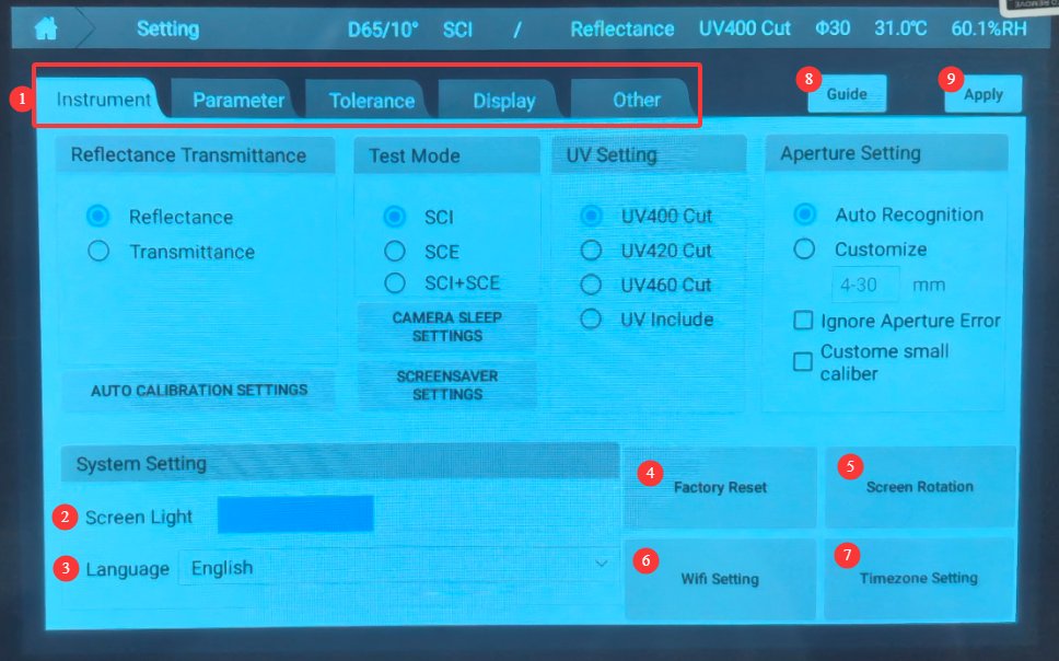
4.4 Introduction to the Settings Interface
図4-10を参照してください。
| 数 | お願い |
|---|---|
| ① | All settings and wizard screens are consistent; see Section 4.1. |
| ② | 画面のバックライト |
| ③ | 表示言語 |
| ④ | 工場出荷時の設定を復元 |
| ⑤ | Flip the screen; tap to rotate the display 180°. |
| ⑥ | Wi-Fi設定 |
| ⑦ | Time zone settings; these will update automatically once connected to the internet |
| ⑧ | Click to return to the wizard interface |
| ⑨ | After making any changes in the settings screen, please click “Apply”; otherwise, the changes will not take effect. |
4.5 Introduction to the Calibration Interface
4.5.1 Calibration Procedure for the Reflectance Measurement Assembly
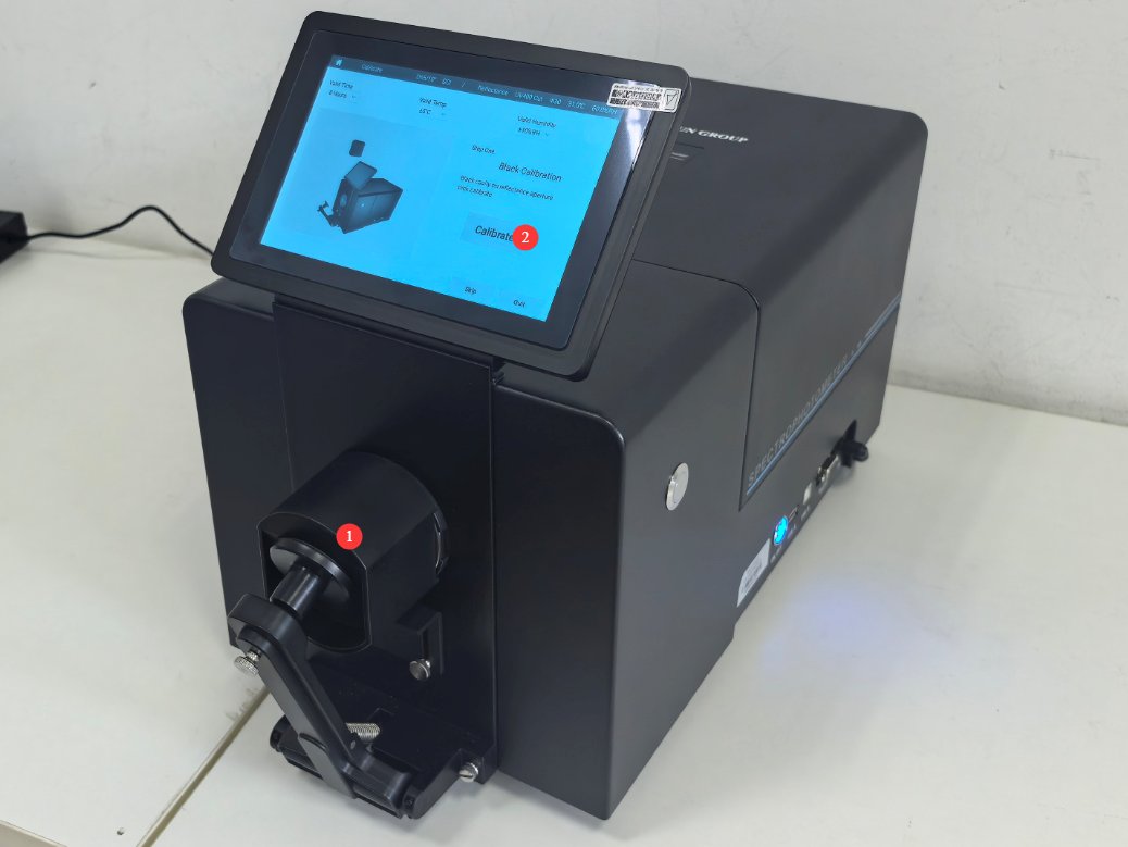
Follow the instructions to perform a black calibration first, as shown in Figure 4-11.
| 数 | お願い |
|---|---|
| ① | Following the on-screen prompts, place the black cavity in the measurement aperture. |
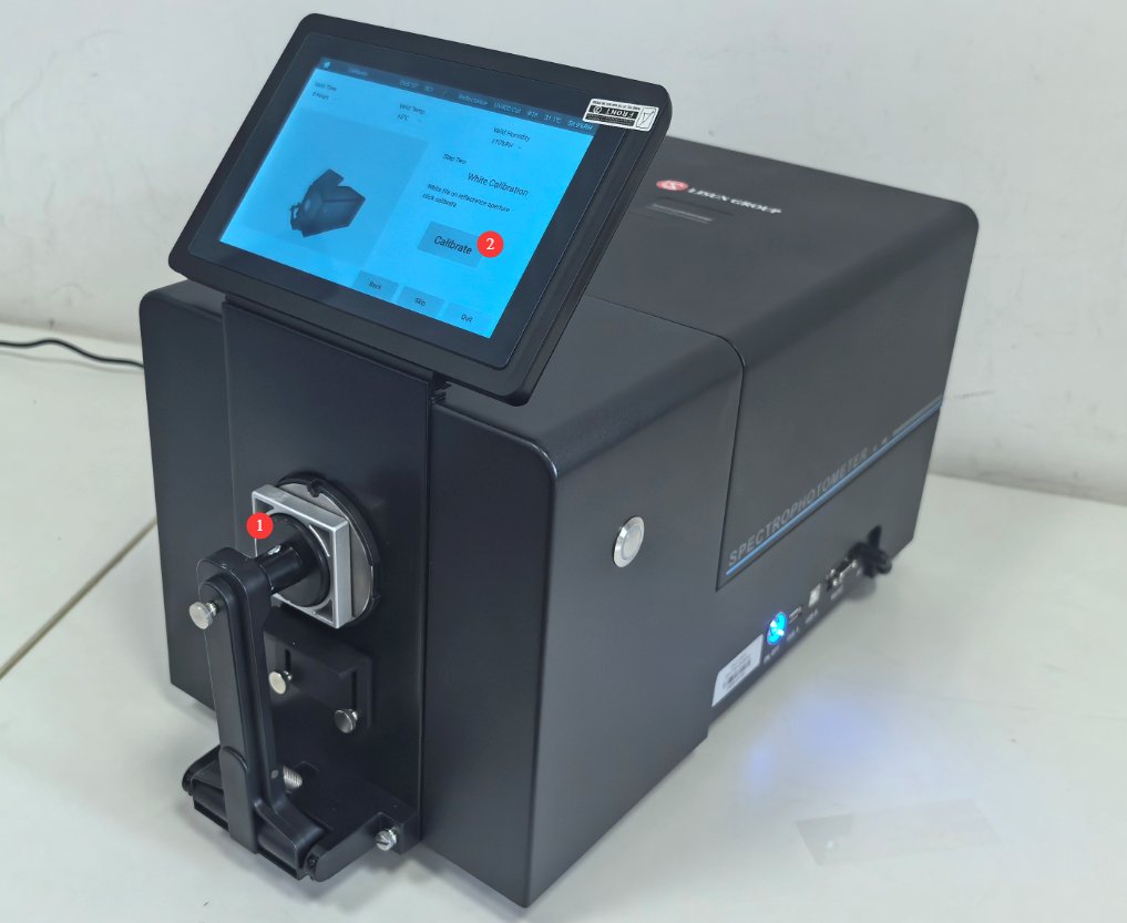
| ② | Click “Calibrate.” After the black calibration is successful, the white calibration screen will appear, as shown in Figure 4-12. |
| 数 | お願い |
|---|---|
| ① | Following the on-screen prompts, place the whiteboard over the measurement aperture. |
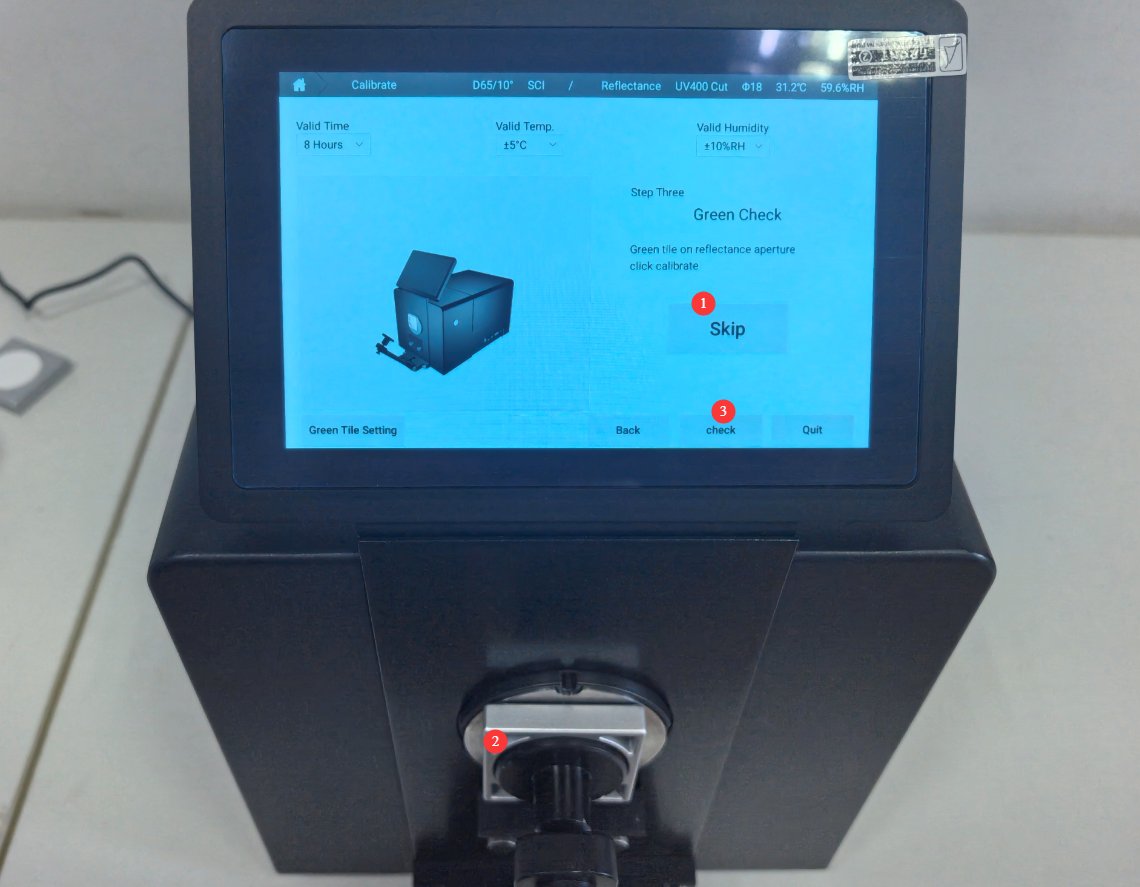
| ② | Click “Calibrate.” Once white calibration is complete, the system will automatically proceed to the green calibration screen, as shown in Figure 4-13. |
| 数 | お願い |
|---|---|
| ① | The green-board verification is a step in validating the instrument’s accuracy; it is not a mandatory calibration procedure. For quick daily tests, you can simply click to skip it. |
| ② | If calibration is required, follow the on-screen prompts and place the green plate securely in the measurement aperture. |
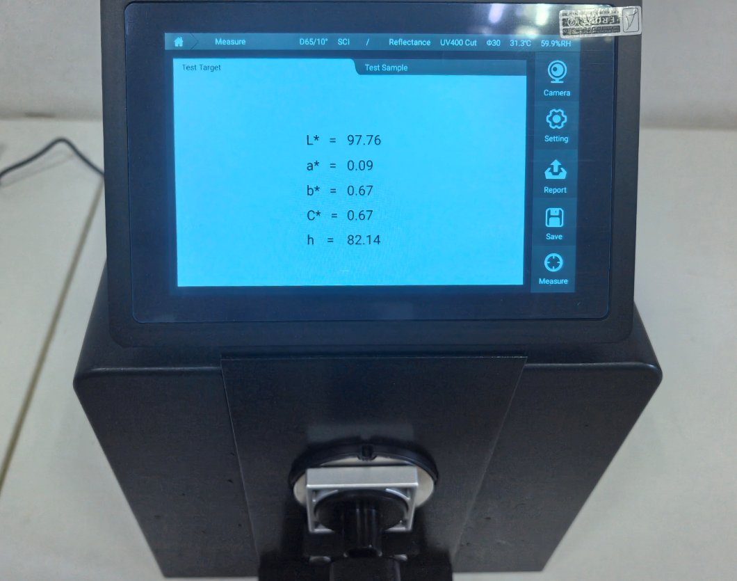
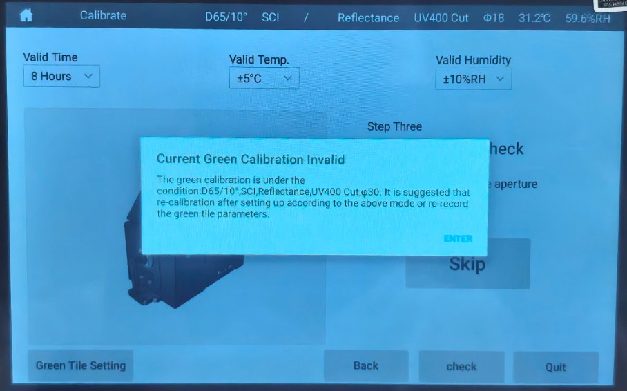
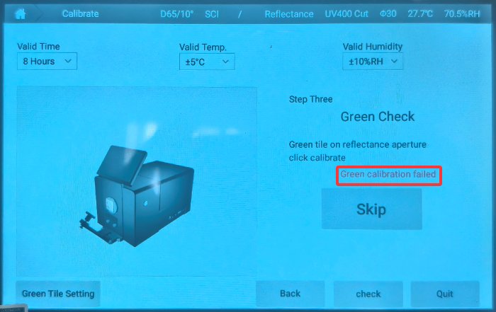
| ③ | Then click “Verify.” If verification is successful, the green plate measurement results will be displayed immediately, as shown in Figure 4-14; Verifying green plate data requires specific measurement conditions. If the conditions are not met, please follow the prompts to adjust the test conditions and try again, as shown in Figure 4-15; if a verification failure is indicated, as shown in Figure 4-16, there may be an issue with the instrument calibration or the measurement. Please check your operating procedures or inspect the black chamber, white plate, or green plate for abnormalities. |
4.5.2 Calibration Procedure for the Transmittance Measurement Assembly
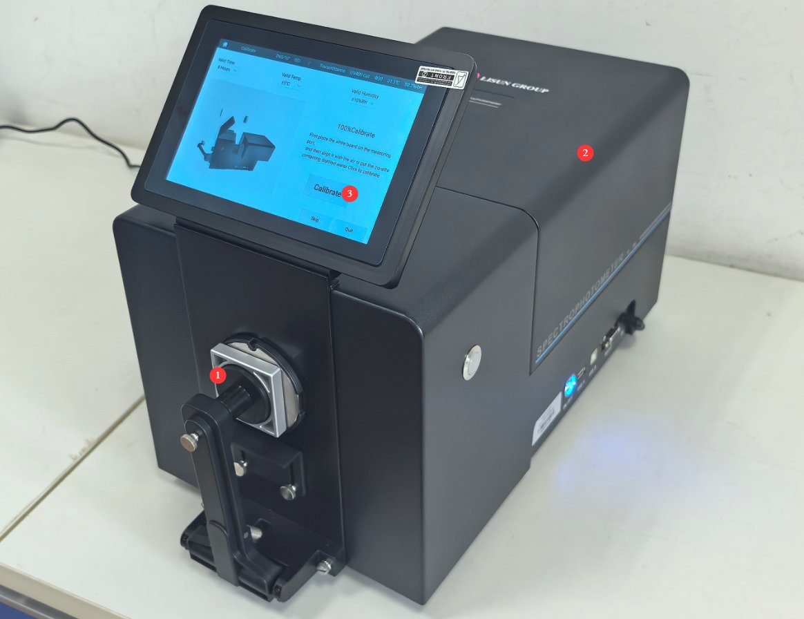
図4-17を参照してください。
| 数 | お願い |
|---|---|
| ① | Follow the on-screen prompts and place the whiteboard over the reflection measurement aperture. |
| ② | No modifications are required at the transmittance measurement aperture; if a cuvette is required for measurement, place a cuvette filled with distilled water at the transmittance measurement aperture during calibration and close the housing. |
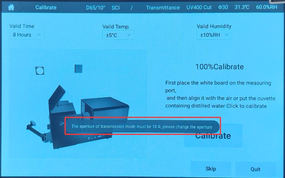
| ③ | Click to calibrate; once calibration is complete, the system will proceed directly to the main menu or measurement interface. When calibrating the transmission component, a reflection measurement aperture of a specific size (18 mm) must be installed. If the aperture size does not match, please replace it as prompted and try again; see Figure 4-18; |
To verify the accuracy of the transmittance measurement, set the measurement parameter to haze to display both haze and transmittance. When measuring an empty cuvette or a cuvette filled with distilled water, the transmittance should be close to 100%.
5. Using the Desktop Software
5.1 Internet Connection and Software Installation
Connect the instrument to the computer using the dedicated USB cable. Copy the software installation package to the computer (Windows 10 is recommended), as shown in Figure 5-1.
| 数 | お願い |
|---|---|
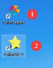
| ① | To install the instrument software, double-click the installer. Once installed, two icons will appear, as shown in Figure 5-2. |
| ② | RS232-USB Adapter Driver; no installation is required when using a USB cable |

| 数 | お願い |
|---|---|
| ① | This is paid color management software; you don’t have to use it. |
| ② | Double-click to open this software. Once it opens, it will automatically connect to the internet. |
5.2 Quick Start Guide for the Software
5.2.1 Introduction to the Software’s Main Interface
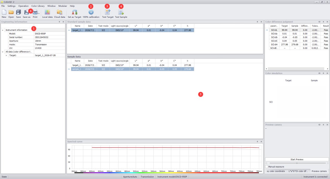
図5-3を参照してください。
| 数 | お願い |
|---|---|
| ① | Instrument Information Display |
| ② | Calibration. Note: The calibration procedures differ between reflection and transmission measurement modes. |
| ③ | Reference Sample Measurement |
| ④ | サンプル測定 |
| ⑤ | Measurement Results Area |
| ⑥ | Save or print the measurement report |
5.2.2 Introduction to the Settings Interface
5.2.2.1 Measurement Parameter Settings Interface
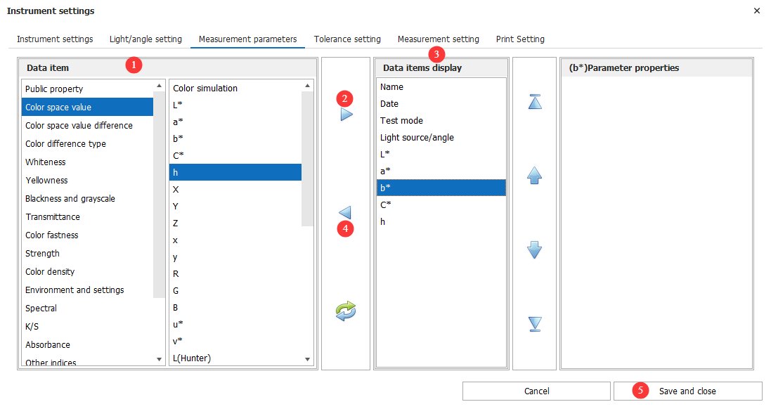
図5-4を参照してください。
| 数 | お願い |
|---|---|
| ① | Selection of Measurement Parameters |
| ② | After selecting a measurement parameter, click the right-pointing arrow to add it to the list of displayed data items, and it will appear on the measurement screen. |
| ③ | Data items displayed |
| ④ | After selecting a data item, click the left arrow to delete it—it will no longer be displayed on the measurement screen. |
| ⑤ | Once you’re done, click “Save” and exit. |
5.2.2.2 Report Printing Settings Interface
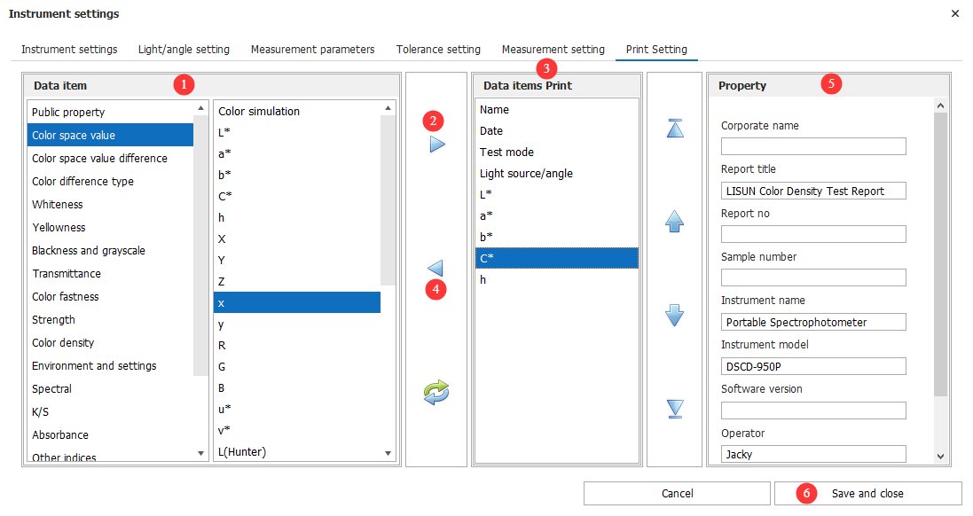
図5-5を参照してください。
| 数 | お願い |
|---|---|
| ① | 印刷設定 |
| ② | After selecting the print parameters, click the right-pointing arrow to add them to the print data items, which will then be printed on the test report. |
| ③ | Data Fields to Print |
| ④ | After selecting the data items to be printed, click the left arrow to delete them—that is, to exclude them from the test report. |
| ⑤ | Fill out the test report information |
| ⑥ | Once you’re done, click “Save” and exit. |
6. Daily Maintenance and Care of Equipment
6.1 クリーニングとメンテナンス
6.1.1 Cleaning the Body and Display
Body Surface: Wipe dust and stains from the body with a clean, soft cloth. For stubborn stains, lightly wipe the area with a small amount of water. Do not use detergents or other corrosive liquids;
Display: Gently wipe the screen with a dedicated screen-cleaning cloth to avoid scratching it. Do not touch the display directly with your fingers. If dust gets on the screen, gently brush it away with a lint-free brush.
6.1.2 Cleaning the Calibration Plate
The calibration plate is a standard accessory; surface wear and stains will affect calibration accuracy: Gently wipe the surface of the calibration plate with a lint-free cloth; if there are stubborn stains on the surface of the calibration plate, contact customer service promptly to have it replaced. Do not sand or repair the calibration plate yourself.
6.2 Calibration Interval Requirements
To ensure the instrument’s measurement accuracy and operational reliability, it is recommended that it be sent periodically to a qualified third-party metrology laboratory for calibration. The recommended calibration interval is 12 months. Users may determine the specific calibration interval based on frequency of use, environmental conditions, and quality system requirements.
Troubleshooting and Resolving Common Issues
| 障害症状 | 考えられる原因 | 手順 |
|---|---|---|
| Calibration Failed | A whiteboard was accidentally placed during black calibration; a black chamber was accidentally placed during white calibration; and transmission calibration was not performed according to the instruction diagram. | Please refer to Section 4.5. Ensure that the factory-supplied black chamber is used for black calibration and the factory-supplied white board is used for white calibration. For calibration in transmission mode, follow the instructions in the instrument’s diagram. |
| 測定誤差 | Tolerance settings may be incorrect | Check the tolerance settings and adjust them |
| 異常な検査結果 | The sample does not fit snugly against the measurement aperture; the sample surface is significantly damaged; in transmission mode, measurements were mistakenly taken using the reflection aperture. | Check that the sample fits snugly and completely against the measurement aperture; inspect the sample’s surface to ensure it is undamaged; verify the measurement mode and set the instrument to the appropriate measurement mode. |
| Caliber Identification Error | The measurement orifice plate was not installed; the orifice plate was installed upside down; a non-standard measurement orifice plate was installed. | Check whether an aperture plate is placed at the instrument’s reflective measurement aperture; check the orientation of the aperture plate; please use the standard measurement aperture plate. |