
 英語
英語 中文简体
中文简体 Русский
 Español
 Português
 Türkçe
 العربية
 Deutsch
 Polski
 Italiano
 Français
 한국어
한국어 ไทย
ไทย Tiếng Việt
 日本語
日本語





























Current Injection Probe and Clamp
ユーザーズマニュアル
適用 LISUN models: LIS-BCP110、LIS-CCF500
1. 機器の基本的な理解
1.1 製品概要
1.1.1 LIS-BCP110ICC Inductively Coupled Clamp
The LIS‑BCP110ICC inductively coupled clamp is a coupling device used for automotive electronic transient immunity testing. It uses inductive coupling to couple a transient pulse 2a(slow pulses) into the harness under test via inductive coupling, without requiring direct electrical contact with the test wires. It is used for transient immunity testing of non-power lines.
Note: ICC coupling clamps are intended solely for slow-pulse 2a (positive/negative) testing and must not be used for 3a or 3b fast-pulse testing. For fast-pulse testing, CCC capacitive coupling clamps must be used.
1.1.2 LIS-CCF500 ICC Calibration Fixture
The LIS-CCF500 is a calibration fixture designed for use with the LIS-BCP110. It is used for calibrating coupling clamps to verify their accuracy and ensure test repeatability.
1.1.3 Description of Key Auxiliary Equipment
The LIS-BCP110 and LIS-CCF500 must be used in conjunction with the LISUN EMS-ISO7637 Automotive Transient Immunity Generator; the EMS-ISO7637 is used to generate slow pulses 2a.
For information on using the EMS-ISO7637, please refer to its operating instructions.
1.2 主な技術仕様
| 機器モデル | Key Parameters |
|---|---|
| LIS‑BCP110 ICC Inductively Coupled Clamp | Frequency range: 4 kHz to 100 MHz; Maximum attenuation: 10 dB; Maximum Input power: 100 W; Connector: N-type coaxial connector |
| LIS‑CCF500 ICC Calibration Fixture | Frequency range: DC–500 MHz; Voltage standing wave ratio: 2:1; Used for calibrating coupling clamps |
1.3 Applicable Standard Provisions and Test Subjects
1.3.1 Applicable Standards and Provisions
GB / T 21437。3-2021 “Road Vehicles—Test Methods for Electromagnetic Disturbances on Electrical and Electronic Components Caused by Conducted and Coupled Disturbances—Part 3: Immunity to electrical transients coupled into non-power lines,” Chapter 4.7, ICC (Inductive Coupling Clamp) test method, including 4.7.2 Calibration, 4.7.3 Wiring Harness Arrangement, and 4.7.4 DUT Test Setup.
ISO 7637-3:2016 Road Vehicles—Electrical Disturbances from Conduction and Coupling—Part 3, Section 4.7: ICC Inductive Coupling Clamp Test.
1.3.2 Applicable DUT (Device Under Test)
Applicable to 12V/24V in-vehicle electrical and electronic components for Class M, N, and O road vehicles: ECUs, sensors, actuators, BMS, in-vehicle gateways, etc. Applies only to non-power signal lines (CAN/LIN, signal input/output harnesses).
2.使用上の注意
2.1 安全上のご注意
2.1.1 電気安全
The LIS-BCP110 has Input power of 100 W. Do not exceed the rated input power under any circumstances, as doing so may burn out the coupling clamp core and coaxial connector. The device must be matched to the output power of the transient generator, and prolonged operation at power levels exceeding the rating is prohibited.
Before making connections, removing the coupling clamps, or adjusting the fixture position, you must turn off the transient pulse generator and disconnect the output to prevent injury from high-voltage transient pulses or damage to the coupling クランプ.
Never insert or remove N-type coaxial connectors while they are energized; keep the connectors dry, and do not touch the internal conductors with your hands to prevent damage from static electricity.
2.1.2 Machinery and Material Handling Safety
The LIS‑BCP110 contains a highly permeable magnetic core; do not drop, strike, or subject the jaws to excessive pressure. A cracked magnetic core will render the coupling clamp inoperable.
The LIS-CCF500 fixture is a precision RF tooling component. Do not drop or strike it. Operate the fixture’s locking knobs gently; do not force them.
2.2 環境要件
2.2.1の環境条件
Operating ambient temperature: 10°C to 40°C; ambient humidity: 30% to 70% RH, no condensation, and free of dust and corrosive gases. Keep away from metal walls and large metal structures to minimize stray coupling interference.
2.2.2 Precautions for Operators
When handling RF coaxial connectors, it is recommended to wear an antistatic wrist strap, as static electricity can damage the interior of the coupling clamp;
Do not touch the magnetic core of the coupling jaws with your hands; oil or metal debris on the magnetic core can alter the coupling performance and cause test results to drift.
2.3 List of Prohibited Operations
Do not route the DUT’s main power supply cable through the LIS‑BCP110;
Do not use ICC coupling clamps to perform 3a/3b fast-pulse tests;
Do not apply continuous input power exceeding 100 W to the coupling clamps;
Do not forcefully close the coupling jaws or twist the N-type RF connector with excessive force;
Do not perform power-on testing when the unit is damp or covered with condensation.
3. 機器の概要と配線
3.1 機器構成
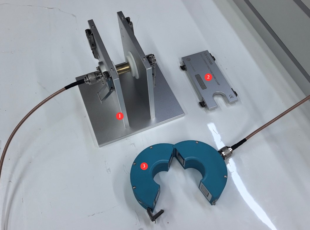
図3-1を参照してください。
| 数 | お願い |
|---|---|
| ① | LIS-CCF500 Fixture Body |
| ② | LIS-CCF500 Fixture Cover Plate |
| ③ | LIS‑BCP110ICC Inductively Coupled Clamp |
3.2 Schematic Diagram of Waveform Verification Connection
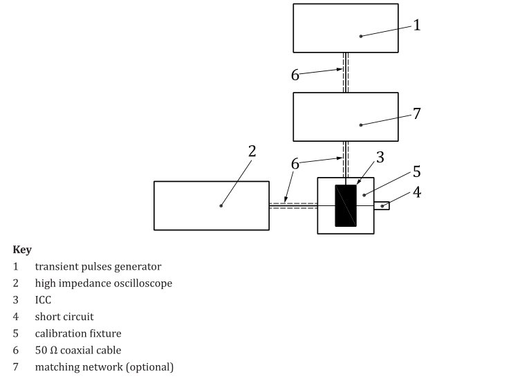
3.2.1 Standard Diagram
See Figure 3-2 (taken from ISO 7637-3, Figure 6).
3.2.2 Product Connection Diagram
図3-3を参照してください。
| 数 | お願い |
|---|---|
| ① | EMS-ISO 7637 Automotive Transient Immunity Generator |
| ② | LIS-BCP110 and LIS-CCF500 |
| ③ | N-Type Short Coupler |
| ④ | Oscilloscope, bandwidth ≥ 100 MHz, used to observe calibration waveforms |
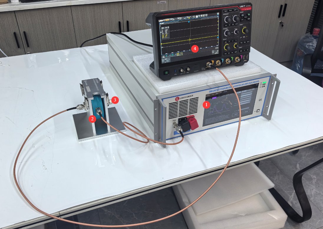
Note: The LIS‑CCF500 fixture and the LIS‑BCP110 coupling clamp are non-directional; this means that even if you set the EMS-ISO7637 to ICC+, the waveform received by the oscilloscope may be ICC-.in which case you simply need to flip the LIS‑BCP110 coupling clamp over and reconnect it.
3.3 Schematic Diagram of the ICC Inductive Coupling Clamp Test Connection
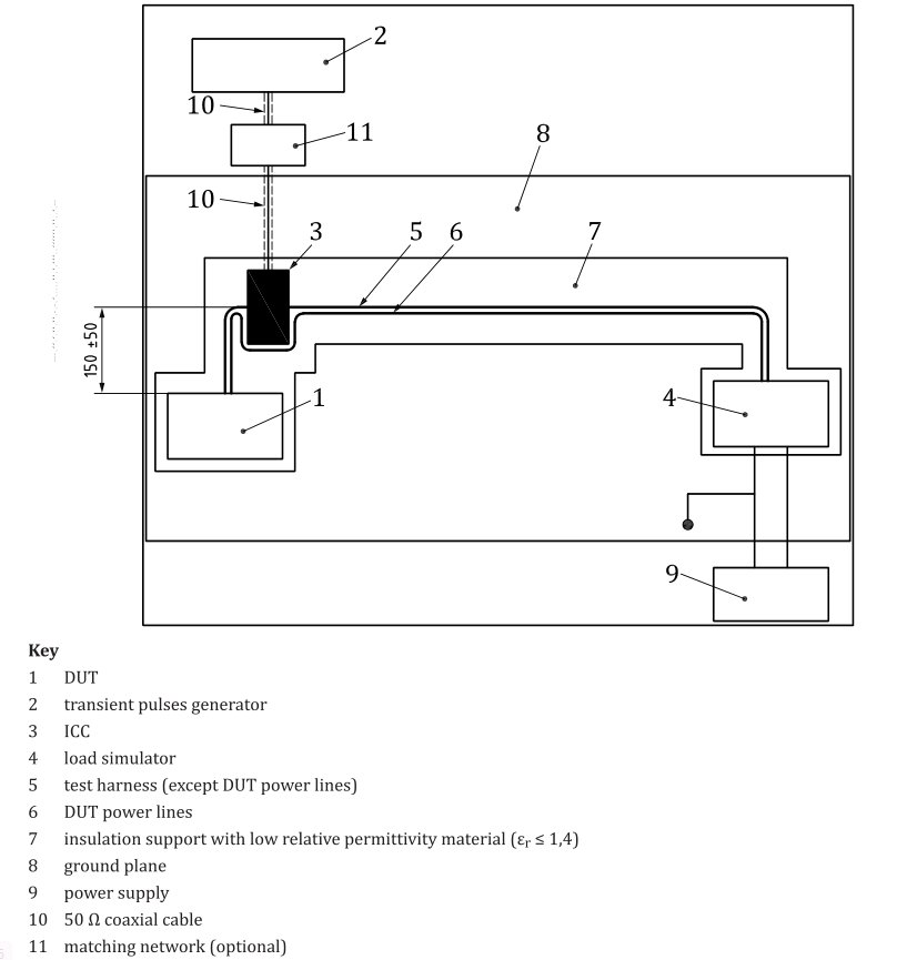
3.3.1 Standard Diagram
See Figures 3–4 (taken from ISO 7637-3, Figure 7).
3.3.2 Product Connection Diagram
See Figures 3–5.
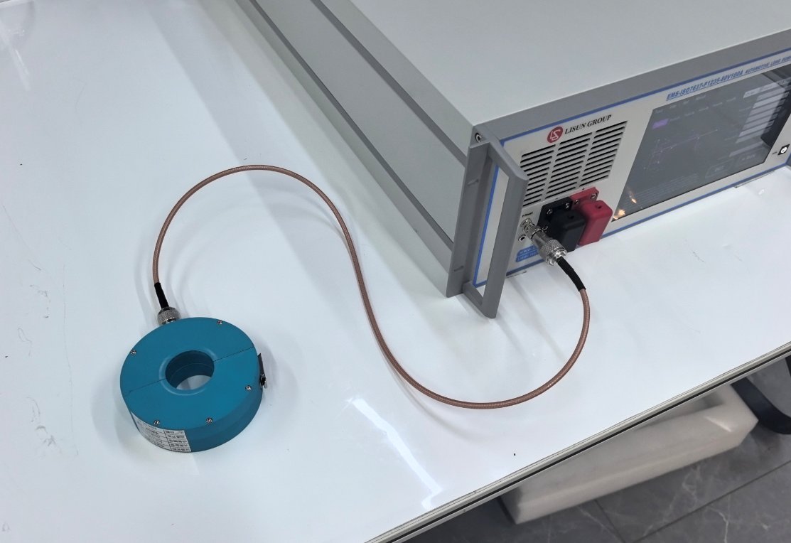
Note: For DUT connection, refer to Section 3.3.1.
4. ICC Inductive Coupling Clamp Test (Pulse 2a Slow Transient Test)
4.1 Test Environment and Grounding Preparations
Place the metal grounding plate flat to ensure proper grounding; place the insulated supports (εr ≤ 1.4) on the grounding plate; place the DUT and wiring harness supports entirely on the insulated components, with the wiring harness positioned 50±5mm above the grounding plate; Total length of the wiring harness: 1700 mm (tolerance: 0 to +300 mm), in compliance with standard requirements.
4.2 Calibration of Coupling Clamps
Refer to Section 3.2 for wiring instructions. Enter EMS-ISO7637 Pulse 2a and set the coupling mode to ICC+ or ICC-.
Observe the waveform on the oscilloscope and record the actual waveform parameters (Us: pulse voltage; tr: rise time; td: pulse width); compare these with the standard 2a pulse parameters to verify that the waveform is correct.
4.3 Preprocessing of the DUT and Wiring Harness
Refer to Section 3.3 for wiring. Connect the DUT according to the vehicle’s actual operating conditions, connecting it to the power supply, all signal harnesses, the simulated load, and the sensor simulator; the DUT’s grounding configuration must match that of the vehicle during installation.
The DUT’s main power line (12V/24V power supply) must never pass through the ICC coupling clamp; only non-power signal harnesses may pass through the coupling clamp.
Place the test harness securely on the insulated support; open the LIS-BCP110 clamp, thread the test harness through the coupling clamp, and close the clamp; the geometric center of the coupling clamp must be 150 ± 50 mm from the DUT connector (mandatory standard distance).
4.4 Executing the Test Process
入るとき EMS-ISO7637 Pulse 2a, ICC+ and ICC- pulse tests must be performed; record all DUT behavior throughout the test, including functionality, alarms, error codes, resets, shutdowns, etc.
4.5 試験結果の評価
Observe and record the operating status of the DUT throughout the test and after its completion, and evaluate the test results according to the following grades:
学年 I (合格): During and after the test, all functions of the DUT operate normally, with no functional degradation, no resets, no error messages, and no stored fault codes; transient, self-recovering phenomena are permitted; where explicitly specified in the product specifications, those specifications shall apply.
学年 II (Conditional Pass): Functional abnormalities occurred during testing; after removing the interference, the DUT recovered automatically, with no hardware damage and no permanent fault codes. Whether this result is considered acceptable must be determined by referring to the product test plan and the automaker’s specifications.
レベル 3 (失敗): Hardware damage, permanent fault codes, the need to power off and restart to recover, or permanent loss of functionality—the DUT is deemed not to meet immunity requirements.
5. 機器の日常的なメンテナンスと手入れ
5.1 Routine Maintenance (After Each Use)
5.1.1 Maintenance of the LIS-BCP110 Coupling Clamp
After testing is complete, use a lint-free soft cloth dipped in a small amount of anhydrous ethanol to wipe the surface of the coupling pliers’ jaws and the outer surface of the N-type connector to remove dust and oil; do not allow liquid to enter the interior of the connector, and do not rinse the body of the coupling pliers;
Check that the jaws open and close smoothly; when closed, the magnetic cores of the jaws should fit tightly together with no noticeable gaps.
5.1.2 Maintenance of the LIS-CCF500 Fixture
Wipe down the fixture with a soft cloth to remove metal shavings and dust;
Apply a small amount of dry lubricant to the locking mechanism; do not use liquid lubricants (to avoid contaminating the RF fixture);
Store in a dry environment and avoid bumping or knocking the calibration fixture.
5.2 保管条件
Storage temperature: –10°C to +55°C; humidity: 20–80% RH, no condensation; store in the original packaging, away from strong magnetic fields and environments with intense vibration; do not stack heavy objects on top of the equipment.
5.3 校正間隔の要件
To ensure the measurement accuracy and operational reliability of the equipment, it is recommended that it be sent periodically to a qualified third-party metrology organization for calibration. The recommended calibration interval is 12 months. Users may determine the specific calibration interval based on frequency of use, environmental conditions, and quality system requirements.
6.よくある問題のトラブルシューティングと解決
| 障害症状 | 手順 |
|---|---|
| The waveform amplitude is insufficient, and the pulse voltage does not reach the target value. | Reclose the coupling clamp and ensure the latch is securely locked; hand-tighten the N-type connector; inspect and replace the coaxial RF cable; clean the surface of the coupling clamp’s magnetic core |
| Waveform jitter, high noise, and poor test repeatability | Check that the ground plate is properly grounded; ensure that the wiring harness and the DUT are kept away from metal obstacles; tighten the LIS-CCF500 fixture knobs to secure the position of the coupling clamps; inspect all RF connectors; keep the test area away from inverters and high-power equipment. |