
 英語
英語 中文简体
中文简体 Русский
 Español
 Português
 Türkçe
 العربية
 Deutsch
 Polski
 Italiano
 Français
 한국어
한국어 ไทย
ไทย Tiếng Việt
 日本語
日本語





























懐中電灯測光器
ユーザーズマニュアル
適用 LISUN モデル: PM400F
1. 機器の開封と基本的な操作方法の説明
1.1 主な技術仕様
| 技術パラメータ | お願い |
| 測定パラメータ | Flash frequency, flash duration, effective luminous intensity, instantaneous maximum/minimum luminous intensity, average luminous intensity |
| Illuminance Measurement Range | 0.1 lx–20000 lx, 4-range automatic range selection |
| 光学測定精度 | Class A/Level 1 (Compliant with JJF 1330-2011) |
| サンプリング・レート | 1 kS/s, 2 kS/s, 5 kS/s, 10 kS/s, 20 kS/s, 50 kS/s, 100 kS/ |
| テスト時間範囲 | 100ミリ秒~10秒 |
| 時間分解能 | 10μs |
1.2 開封検査および付属品の確認
1.2.1 開梱と目視検査
デバイスの開梱時には、鋭利な工具などで外装を傷つけないよう、優しく扱ってください。開梱後、まずデバイスの外観を点検し、目に見える変形やへこみがないか、ボタンが破損または緩んでいないかを確認してください。デバイスまたは付属品に異常が見られる場合は、電源を入れずに直ちにご連絡ください。
1.2.2 本体および付属品
| 数 | お願い |
| ① | PM400F 測光器 |
| ② | Light-Blocking Tube |
| ③ | USBケーブル |
| ④ | 電源アダプタ |
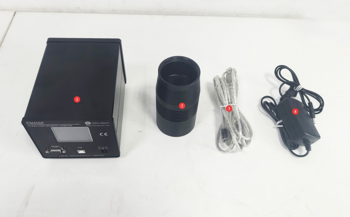
図1
Download links for the digital user manual, software, warranty card, and other materials have been sent via email. Please download them as soon as possible. If you missed the email, please feel free to contact us to request the download links again.
1.4 Applicable Test Scenarios
Aerospace sector: Aircraft navigation lights, anti-collision lights (compliant with HB6490-1991), and aviation obstruction lights (compliant with MH/T 6012-1999).
Transportation Sector: Traffic warning lights, navigation lights (compliant with JTT 761—2022).
Other fields: flare bombs, signal flares, pulsed LEDs, pyrotechnic explosives, and other pulsed light sources (compliant with ECE R65 and JJF1330-2011).
2.使用上の注意
2.1 Safety Operating Procedures
2.1.1 電源の安全性
You must use the included DC 5V/1A power adapter. Never use a power source with incompatible voltage or current, to prevent damage to the device.
2.1.2 環境安全
It is strictly prohibited to operate equipment in explosive atmospheres or areas where flammable and explosive materials are stored, as the operation of electrical equipment may cause safety incidents.
Avoid using the device in environments with strong electromagnetic interference (such as near high-power motors or radar systems) to prevent affecting the accuracy of measurement data.
The surface of the equipment may become slightly warm during operation. Avoid covering it with foreign objects, ensure adequate ventilation, and prevent damage caused by overheating.
2.2 Contraindications for Use
The equipment has been calibrated before leaving the factory. Users are strictly prohibited from performing calibration operations on their own, as this may compromise measurement accuracy.
Do not remove any exterior components from the device. High voltage is present inside the device, and disassembly by non-professionals may result in personal injury or damage to the device.
The probe surface is a precision optical component; do not touch or scratch it with your hands, and avoid wiping it with corrosive cleaning agents.
2.3環境要件
Operating Environment Conditions: Temperature: 18°C to 30°C; Humidity: 35%RH to 75%RH.
Storage Conditions: Temperature: -20°C to 50°C; Humidity: ≤90% RH.
Testing must be conducted in a darkroom, where stray light must be ≤0.01 lx to prevent ambient light from interfering with the measurement results (this is particularly important during low-light measurements).
The test distance between the light source under test and the detector must be adjusted according to the light source’s intensity (for example, the distance may be appropriately increased for a strong light source), and the light-emitting surface of the light source must be aligned directly with the center of the detector’s window.
2.4その他
本マニュアルに記載されていない事項については、慎重に進めるか、弊社までお問い合わせください。
3. Hardware Operations
3.1 PM400F 組み立てと配線
3.1.1 Assembly of the Light-Blocking Cylinder
| 数 | お願い |
| ① | Remove the probe cover |
| ② | Hold the light-blocking cylinder and rotate it clockwise while aligning it with the detector window until it is fully tightened, ensuring there is no play or gaps that allow light to leak through. |

図2
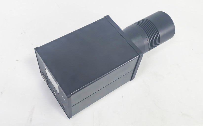
図3
3.1.2 Introduction to the PM400F Front Panel and Wiring
| 数 | お願い |
| ① | Touchscreen displaying real-time test data, parameter settings, etc . Note: Do not adjust any parameters without authorization to avoid causing test abnormalities. |
| ② | RS-485 communication port—required when used with a Goniophotomoeter; if you have purchased only the PM400F, you do not need to use this port. |
| ③ | USB port; connect to a computer using a USB cable to communicate with the software |
| ④ | Power adapter port—please connect the power adapter |
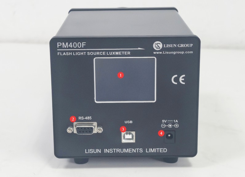
図4
Note 1: Please use only the original USB cable to connect the PM400F directly to your computer whenever possible. Do not use other USB extension cables, USB adapters, or similar devices, as they may cause the software to malfunction.
Note 2: The PM400F can be powered via a USB cable; however, in some cases, the USB power supply may be unstable. Therefore, you should also connect the power adapter to ensure a stable power supply. If the power supply is unstable, the device or software may malfunction. We recommend connecting both the USB cable and the power adapter at the same time.
3.2 Laboratory Layout
その PM400F must be used in a darkroom environment. Position the light-emitting surface of the luminaire being tested directly in front of the PM400F probe, for example, at a distance of 3 meters. If the luminaire emits a strong light, the test distance may be appropriately increased.
Please connect the power adapter to the PM400F、接続します PM400F to your computer using a USB cable, and then operate it using the software.
4. ソフトウェアの操作
4.1ソフトウェアのインストール
4.1.1 Computer Requirements
| カテゴリー | 特定の要件 |
| オペレーティングシステム | Windows 7/8/10/11 (32-bit or 64-bit) |
| ハードドライブスペース | Free space ≥ 100 MB |
| API Requirements | At least one USB 2.0 or higher port |
| その他 | You should log in to your computer using an administrator account whenever possible; otherwise, the software may malfunction. |
4.1.2ソフトウェアのインストール
Below are the software and drivers for the PM400F. Simply double-click each one to install it.
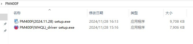
図5
Open “Device Manager” on your computer. If you see “LISUN GROUP Devices” > “Lisun FLASHLIGHT TESTER,” the software and driver have been installed successfully.
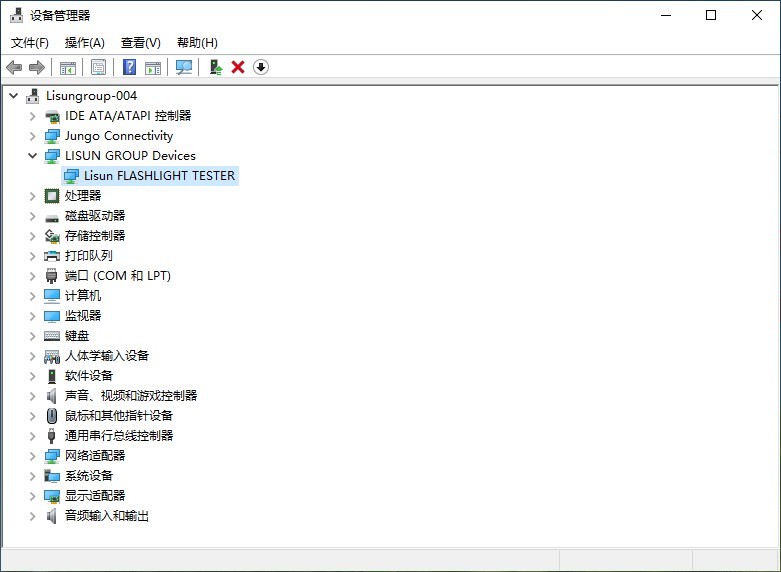
図6
4.2 ソフトウェア設定
4.2.1キャリブレーション
重要な注意: PM400F has been calibrated before shipment; please do not perform any calibration procedures.
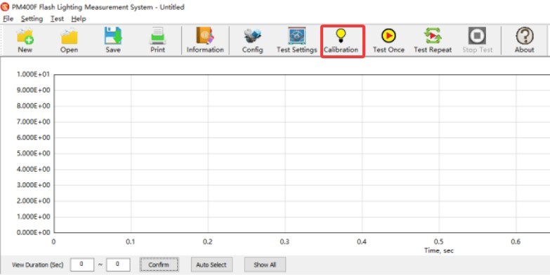
図7
4.2.2システム構成
Click “System Configuration.”
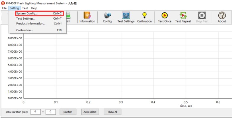
図8
Communication Settings: Select “USB” as the connection type, click the device serial number drop-down menu, and the device number will be automatically retrieved (make sure the device is powered on and connected).
Data Processing and Display.
| 数 | お願い |
| ① | Waveform display range: Default “Auto Select”; number of display cycles set to 8 |
| ② | Method for Calculating Effective Illuminance: The default selection is “Blondel-Rey-Douglas” (recommended by the International Civil Aviation Organization and compliant with relevant standards). |
| ③ | Remove Background Light: Check this box to eliminate the effect of ambient stray light on the measurement. |
| ④ | Pulse train dark time: Default 20 ms (times longer than this are not considered pulse trains) |
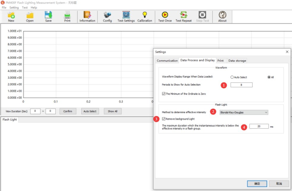
図8.1
Storage Settings.
| 数 | お願い |
| ① | Check the box to enable the auto-save feature |
| ② | 保存場所を選択 |
| ③ | Test File Naming Conventions |
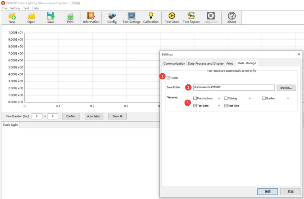
図9
Note: Files saved automatically are in FLM format and can only be opened and viewed using the PM400F ソフトウェアを使用して、WindowsXNUMX XNUMXビット上で動作する XNUMXTB RAID XNUMX を備えたデスクトップ コンピューターで録画されます。
4.2.3テストのセットアップ
| 数 | お願い |
| ① | Click “Test Settings” |
| ② | Photometric type: Select “illuminance” or “luminous intensity” based on testing requirements (luminous intensity is commonly used for testing navigation lights and obstruction lights). |
| ③ | Test Distance: Enter the actual distance (in meters) from the probe surface to the light source being measured. This value must match the actual setup (e.g., 3 m). |
| ④ | Sampling rate: The default is 20 kS/s. If you are testing light sources with high flash frequencies and short durations (such as pulsed LEDs), you can set it to 50 kS/s or 100 kS/s. |
| ⑤ | Sampling duration: 1 to 200 seconds; must be longer than the flash cycle (recommended settings are 5 or 10 seconds to balance test efficiency and data integrity) |
| ⑥ | Range: Set to “Auto” |
| ⑦ | Test Start Mode: The default setting is “Auto Start.” For special samples (such as flash grenades), you can select “Automatic Signal Trigger” and set the trigger threshold (which must be higher than the background light signal). |
| ⑧ | If you set a warm-up time, and the light source under test requires a certain amount of time to stabilize after being turned on, you can set the appropriate warm-up time. A value of 0 means no warm-up. |
| ⑨ | Interval between consecutive tests; if consecutive testing is required, the time interval between two tests |
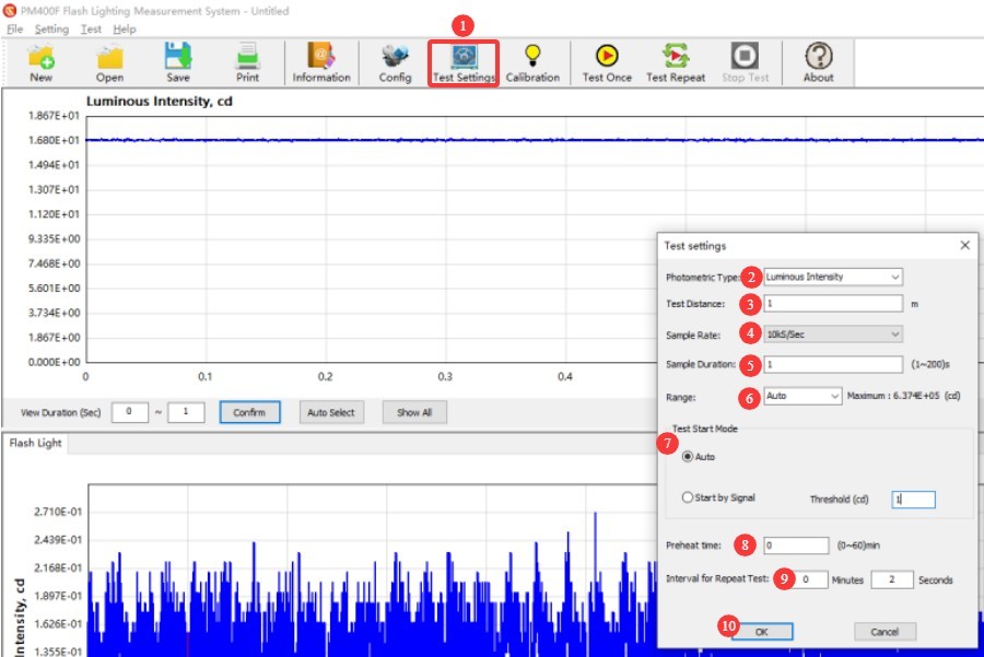
図10
4.3 Start/Stop Test
4.3.1 起動テスト
For unknown samples, click to perform a “single test,” then wait for the sample to emit a light signal, and the software will automatically perform the test.
For standard samples, testing can begin immediately after the sample is illuminated. Click to perform a “Single Test” or “Repeat Test.”
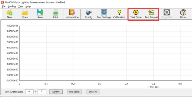
図11
4.3.2 Stopping the Test
After the test is complete that day, you can unplug the PM400F power adapter or turn off the outlet switch. Then, shut down the computer to completely cut off power to the PM400F.
4.4 Processing Test Reports
Click to enter sample information.
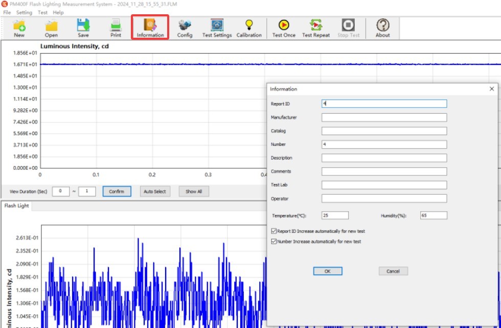
図12
You can set different display time intervals to zoom in or out on the light intensity curve.
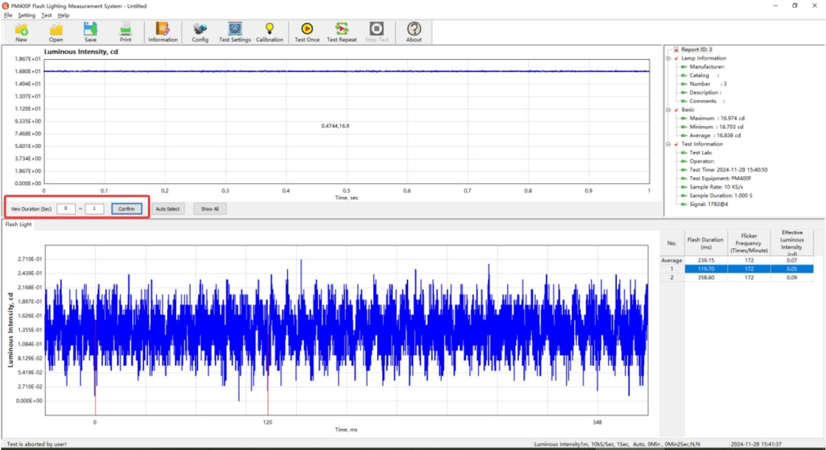
図13
Click “Save As.”
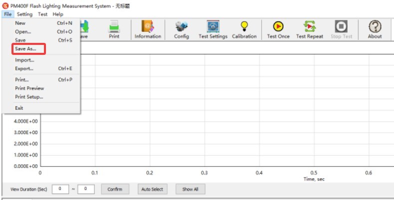
図14
You can save the test data as a CSV or TXT file.
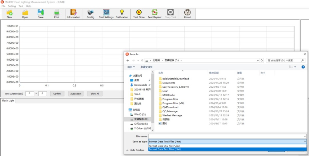
図15
If your computer is connected to a printer or has a PDF printer installed, click “Print” to print the test report.
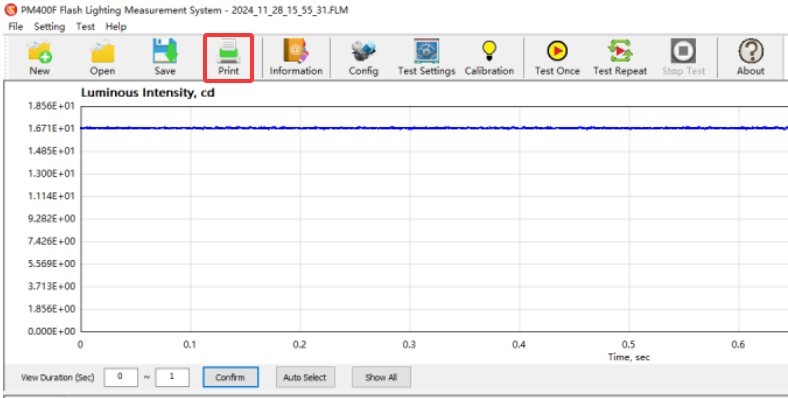
図16
The test report template is shown below.
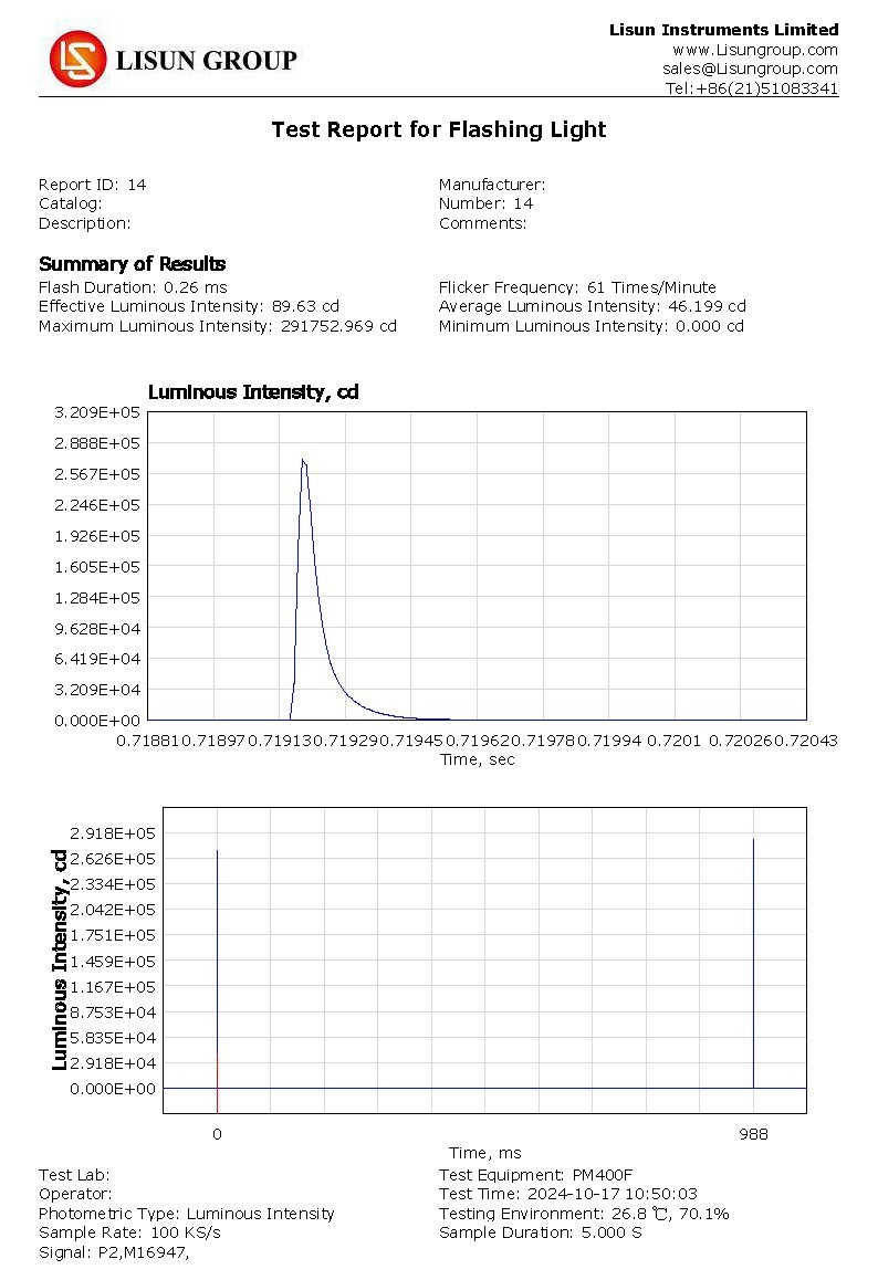
図17
4.5 Analysis of Key Parameters in Test Reports
The results for the following key parameters all comply with the definitions in the relevant standards:
Flash Duration: Measured in “ms,” this value represents the duration of the flash from start to finish (e.g., 0.26 ms).
Flash frequency: Measured in “flashes per minute,” this indicates the number of flashes per minute (e.g., 61 flashes per minute).
Effective luminous intensity: Measured in “cd”; the equivalent luminous intensity value obtained using a selected calculation method (such as the Blondel-Rey-Douglas method).
Average luminous intensity: Measured in “cd”; the average luminous intensity over one flash cycle.
Maximum/Minimum Luminous Intensity: Measured in “cd,” representing the peak and valley values of luminous intensity within a single cycle.
5. 機器の日常的なメンテナンスと手入れ
5.1。XNUMX日常のメンテナンス
Keep the darkroom control room clean and dust-free to prevent dust from entering the equipment. If there is surface dust on the equipment, wipe it off with a dry, soft cloth.
暗室を長時間高湿度にさらさないようにしてください。必要に応じて除湿機を用意してください。
5.2 Cleaning the Photometric Probe
If the darkroom cannot be kept dust-free, clean the photosensitive surface of the photometer probe regularly (for example, once a month) based on actual conditions to prevent dust from accumulating and affecting test accuracy.
清掃の際は、ホコリを取り除き、機器に傷がつかないよう、糸くずの出ない専用の布をご使用ください。
5.3 長期的な廃止措置と保守
5.3.1 機器の清掃と保護
Thoroughly clean the surface, and store the PM400F and connecting cables separately in their own packaging.
5.3.2 月次電源投入
Conduct a test by powering the system on once a month to ensure it is operating normally.
よくある問題のトラブルシューティングと解決
6.1 Communication Failure (Software Cannot Recognize the Device)
| 障害症状 | 考えられる原因 | トラブルシューティング方法 |
| Lisun FLASHLIGHT TESTER” is not listed in Device Manager | The driver is not installed or the installation failed. | Reinstall the driver and make sure the installation is successful. |
| The driver installed successfully, but the software cannot connect. | Unstable or insufficient power from the USB cable | Please connect the power adapter at the same time to ensure a stable power supply. |
6.2 Software Crashes on Startup
| 障害症状 | 考えられる原因 | トラブルシューティング方法 |
| The software does not respond when double-clicked, or an error message appears | System environment incompatibility, incomplete software installation | 1. Verify that your operating system meets the requirements (Windows 7 or later); 2. Uninstall the software and reinstall it (run the installer with administrator privileges); 3. Turn off your computer’s firewall and antivirus software, then try again |
6.3 High/Low Measurement Values
| 障害症状 | 考えられる原因 | トラブルシューティング方法 |
| The data is generally on the high side | Background light and probe contamination not accounted for | 1. Check the “Remove Background Light” option in the software and retest; 2. Clean the light-sensitive surface of the photometer probe; 3. Check for stray light in the darkroom and ensure it meets the requirements. |
| The data is generally on the low side | Incorrect test distance setting, improper range selection | 1. Verify the test distance to ensure that the software settings match the actual setup; 2. Switch to a higher range (e.g., from Range 1 to Range 2) and retest; 3. Check whether the sample has stabilized; if not, extend the warm-up time. |
6.4 Displays “—-” (out of range)
| 障害症状 | 考えられる原因 | トラブルシューティング方法 |
| テスト中、 PM400F displays “—-” | The light source intensity exceeds the current range | 1. Change to a wider measurement range (e.g., switch from auto-range to range 4); 2. Increase the test distance (e.g., from 3 m to 5 m); 3. If the measurement still exceeds the range, please contact us to purchase an attenuator. |
6.5 Troubleshooting Error Codes
| トラブルシューティングコード | 障害の説明 | 考えられる原因 | トラブルシューティング方法 |
| Insufficient data returned! (52) | Incomplete data transfer | Insufficient power from the USB port | 1. Replace the USB port on the back of the computer; 2. Shorten the USB cable (≤5 meters) |
| Insufficient return data! (49) | 同上。 | ||
| Insufficient return data! (5b) | The USB cable is too long | Replace the USB cable with one that is 5 meters or shorter, and reconnect it. |