
 英語
英語 中文简体
中文简体 Русский
 Español
 Português
 Türkçe
 العربية
 Deutsch
 Polski
 Italiano
 Français
 한국어
한국어 ไทย
ไทย Tiếng Việt
 日本語
日本語





























Articulate Probe
ユーザーズマニュアル
適用 LISUN models: SMT-355F101D1、SMT-355F101D2
1. “Test” refers to Basic understanding.
1.1 適用規格
The SMT-355F101D1 toddler hand-shaped probe is designed and manufactured in strict accordance with UL 60335-2-24 Figure 101. DVA.1, and is fully matched to the hand size parameters and joint mobility characteristics of children aged 3.5 to 4.5 years as specified in the standard. All critical dimensions comply with the standard’s tolerance requirements, making it suitable for direct use in child accessibility testing under the provisions of this standard.
The SMT-355F101D2 probe for older children’s hands was designed and manufactured in strict accordance with UL 60335-2-24 Figure 101. DVA.2, corresponding to the physiological hand parameters of children aged 10.5 to 11.5 years. The dimensions and structure fully replicate the standard illustration, meeting compliance requirements for reachability testing of refrigeration products by older children.
1.2つのコア機能
Used to simulate the hand shapes and insertion motions of children of different age groups, these probes verify the protection performance of moving parts in refrigeration appliances, ice cream machines, ice makers, and other products, and assess the risk of children accidentally touching hazardous components. Each probe set includes two configurations—a flat hand and a conical hand—to accommodate test scenarios with various opening shapes, making it an essential tool for home appliance safety testing, product R& D validation, and certification testing.
1.3 電子文書のダウンロード
電子版ユーザーマニュアル、校正証明書、保証書、その他の書類のダウンロードリンクは、出荷時にメールにて既にお送りしております。お早めにダウンロードしてください。メールが届いていない場合は、再度ダウンロードリンクをお送りしますので、弊社までご連絡ください。
2.安全上の注意
2.1 Test Environment Requirements
Tests should be conducted in a dry, dust-free indoor environment with an ambient temperature between 10°C and 35°C and a relative humidity not exceeding 75%. The test bench should be level and non-slip, with no obstacles around it and sufficient space reserved for operation. Do not use this probe in flammable or explosive environments.
2.2 Personnel Safety Requirements
Operators must complete basic training in safety testing and be familiar with the relevant provisions regarding mechanical hazard testing in the UL 60335-2-24 standard.
When testing the accessibility of live parts, the power to the equipment under test must first be turned off; under no circumstances should the probe be used to touch live areas with bare hands while the equipment is energized.
When testing moving parts, first insert the probe while the equipment is shut down, then start the equipment and observe; never force the probe into the equipment while it is running at high speed to prevent the probe from being drawn in and causing hand injuries.
When operating the device, hold it by the insulated handle and avoid direct contact with the metal probe to prevent accidental electric shock or scratches.
2.3 Equipment Safety Requirements
The device under test must be placed on a stable surface and must not shift or tip over during testing.
Before testing, verify that the protective covers on the moving parts of the device under test are intact to prevent parts from flying out and causing injury during the test.
Do not use the probe as a prying or striking tool to prevent deformation, failure, or breakage.
When testing samples with sharp edges, control the force with which the probe is inserted to prevent the probe from becoming jammed by the sample’s edges and suffering permanent deformation.
2.4 Contraindications for Probe Use
Do not drop or throw the probe under any circumstances to prevent damage to its joints and loss of dimensional accuracy.
Do not allow contact with corrosive chemicals such as strong acids and strong alkalis to prevent surface corrosion and material damage.
Do not disassemble, grind, or modify any structural components of the probe on your own; doing so will invalidate its metrological validity.
If the probe shows significant deformation, joint seizure, or severe rust, it must not be used for compliance testing.
3. Probe Overview
3.1 標準図
3.1.1 SMT-355F101D1
See Figure 3-1 (taken from UL 60335-2-24, Figure 101. DVA.1).
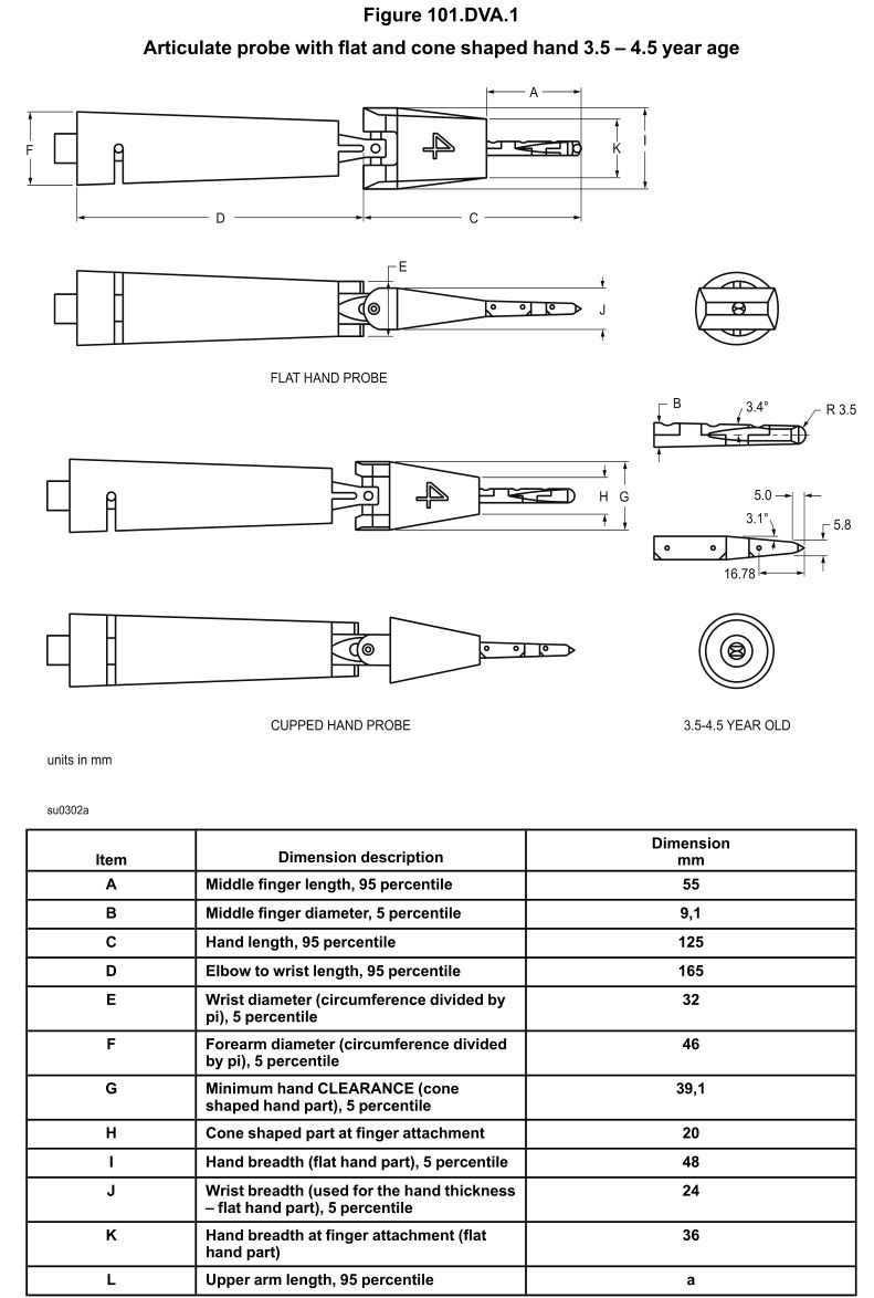
図3-1
3.1.2 SMT-355F101D2
See Figure 3-2 (taken from UL 60335-2-24, Figure 101. DVA.2).
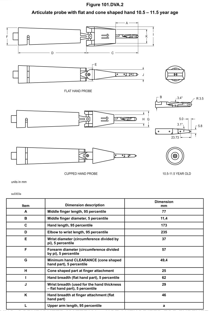
図3-2
3.2 実物の写真
3.2.1 SMT-355F101D1
図3-3を参照してください。
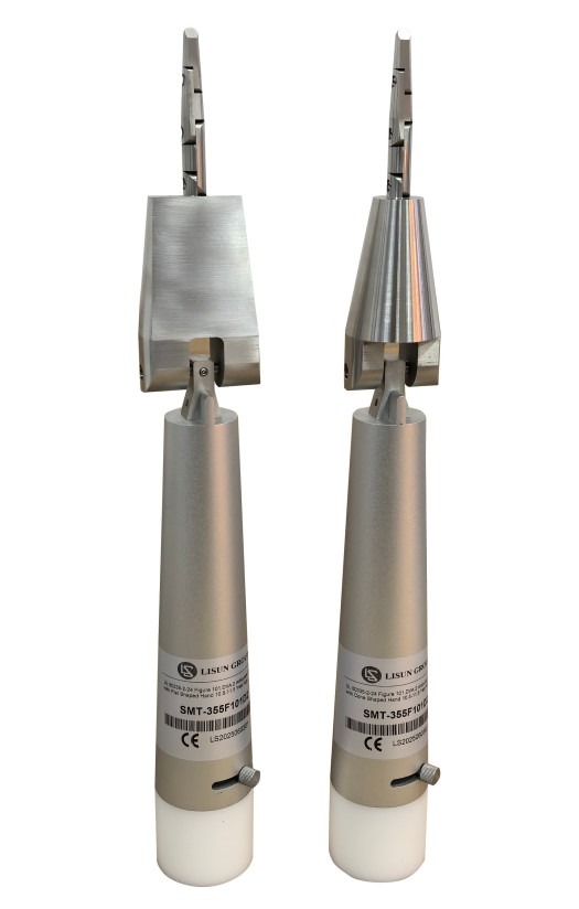
図3-3
3.2.2 SMT-355F101D2
図3~4を参照。
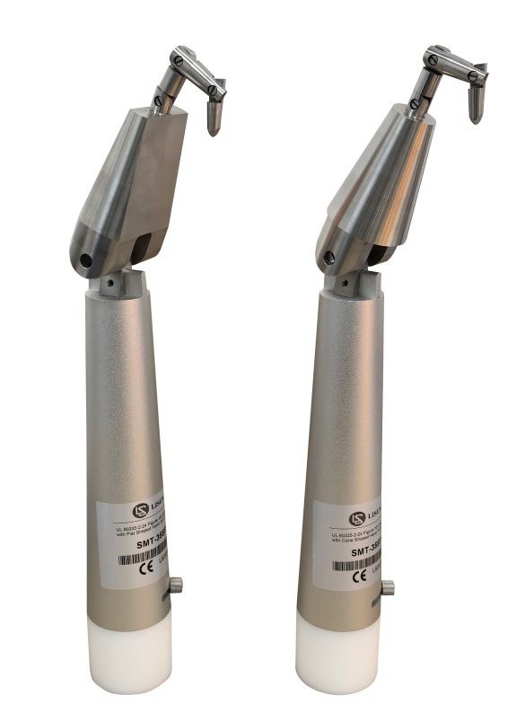
図3-4
4.試験前の準備
4.1 試験試料の準備
4.1.1 Sample Condition Requirements
The device under test must be fully assembled, with all enclosures, covers, and grilles in place and all screws securely fastened.
Connect the power supply according to the product’s rated voltage, allow the equipment to reach its normal operating state, and ensure that the moving parts reach their rated speed.
Before testing, verify that the equipment does not produce any unusual noises or vibrations, and ensure that it operates stably during the test.
If testing multiple locations, mark all openings and gaps to be tested in advance to avoid missing any.
4.1.2 Determination of the Test Area
In accordance with the requirements of the UL 60335-2-24 standard, testing focuses on the following areas: all ventilation openings and heat dissipation grilles on the front, sides, and top of the unit that are within a child’s reach; openings near moving parts such as the ice tray inlets and outlets and the ice dispenser; gaps on the bottom and back where a child might lie down or reach in; and internal openings exposed after removing detachable covers.
4.2 Preparing Auxiliary Tools
Before testing, prepare the following tools: flashlight / industrial endoscope: used to observe the internal contact conditions after the probe is inserted; force measurement device (optional): used to precisely control the thrust applied by the probe; insulated gloves (for testing live parts).
5. Probe Test Procedure
5.1 General Principles for Testing
Tests should be conducted from all possible insertion angles, including vertical, angled, and bent insertion, among other positions;
The thrust applied when the probe is inserted should simulate the hand strength of children in the corresponding age group; for young children, the probe thrust should not exceed 10 N, and for older children, the probe thrust should not exceed 20 N;
While inserting the probe, the angle of the joint may be adjusted as needed to simulate a child’s finger-picking and probing motions; however, do not use force to push it in;
Tests should be conducted at the same test location using both flat and conical hand-shaped probes; the test is considered passed only if both types pass.
5.2 SMT-355F101D1
5.2.1 Operating Procedures for Flat-Tip Probes
Hold the probe by its insulated handle, align the flat part of your palm with the opening to be tested, and keep the plane of your palm parallel to the long side of the opening; push the probe forward with even, slow pressure while bending your knuckles appropriately based on the depth of the opening; Once the probe has been advanced to the limit position (where the wrist can no longer be extended further), hold this position for 5 seconds; observe from multiple angles to determine whether the tip of the probe comes into contact with any hazardous moving parts or live parts; slowly withdraw the probe and record the test results.
5.2.2 Operating Procedures for Conical Hand-Shaped Probes
Hold the insulated handle and align the tapered tip with the center of the circular or irregular opening; push forward at a steady pace, rotating the probe slightly to simulate a child’s rotating finger movement; stop when the tapered tip reaches the point where it can no longer be inserted further, and hold this position for 5 seconds; Adjust the angle of the probe and attempt to insert it from different directions, covering all edges of the opening; after confirming that there are no hazardous components to contact, slowly withdraw the probe and record the results.
5.2.3 Test Angle and Force Application Requirements
Test Angles: The test must cover four typical angles—0° (vertical), 30°, 45°, and 60°—with each angle tested; Applied Force: The standard force is 5 N ± 1 N; the maximum force must not exceed 10 N to avoid false results caused by excessive force; Insertion Depth: The probe should be inserted by allowing it to advance naturally; do not force it in by squeezing the casing until it deforms.
5.3 SMT-355F101D2
5.3.1 Operating Procedures for Flat-Tip Probes
Ensure you are using the D2 probe designed for older children. Hold the end of the handle firmly to keep it steady; position the flat palm of your hand toward the opening to be tested, and slowly insert the probe along the long side of the opening; use the probe’s long forearm-like structure to test the protection of components in deeper locations; Adjust the angle using your wrist joint to simulate the motion of an older child bending their arm to reach inside; after pausing to observe, withdraw the probe smoothly and check the probe tip for any signs of contact with live parts or moving parts.
5.3.2 Operating Procedures for Conical Hand-Shaped Probes
Align the tip of the conical probe with the test opening and push it in with even pressure; While pushing, gently wiggle the probe up, down, left, and right to simulate a child’s hand movements during exploration; once the maximum insertion depth is reached, rotate the probe 360° to confirm that no hazardous components are accessible in any direction; for grating-type structures, test each grating opening individually, ensuring none are omitted.
5.3.3 Test Angle and Force Application Requirements
Test angles: Same as Type D1, covering four angles: 0°, 30°, 45°, and 60°; Applied force: The standard force is 10 N ± 2 N; the maximum force must not exceed 20 N; Precautions: Since the D2 probe is larger and longer, avoid excessive bending of the probe during operation to prevent deformation of the joint due to stress.
5.4 Criteria for Evaluating Test Results
5.4.1 Accessibility Assessment
If any of the following conditions occur, the hazardous component at that location is deemed accessible, and the sample fails inspection: the tip of the probe can come into contact with the area of rotation or reciprocating motion of a moving part; the metal portion of the probe can come into contact with a live part; after the probe is inserted, a moving part can pinch the probe or cause it to move; the probe can pass through an opening and come into contact with high-temperature components whose temperature exceeds the safety limit.
5.4.2 Determination of Conformity
A test location is deemed acceptable if all of the following conditions are met: neither the flat-hand nor the conical-hand probes can reach any hazardous components; the non-reachability requirement is met at all test angles; the housing and grille show no permanent deformation or damage during the test; and the probes do not become stuck or jammed.
6. Daily Maintenance and Care of the Probe
6.1 Daily Cleaning Guidelines
Wipe the entire probe with a dry, clean, soft cloth to remove dust and fingerprints. If the probe comes into contact with oil or water, gently wipe it with a soft cloth dampened with a neutral detergent, then dry it with a dry cloth. Use a soft-bristled brush to clean dust from the joints; do not rinse directly with water. After cleaning, place the probe in a dry, well-ventilated area to air dry, and ensure it is completely dry before storing it.
6.2 Joint Lubrication and Maintenance
Lubrication Interval: Under normal use, lubricate once every 3 months; for frequent use (more than 5 times per week), lubricate once a month;
Lubricant: Use food-grade anti-rust lubricating oil or precision instrument oil; do not use grease that is too thick;
Lubrication Instructions: Apply 1/2 drop of lubricant to each joint pin, rotate the joint 10–15 times to ensure the lubricant penetrates thoroughly, and finally wipe off any excess lubricant from the surface.
6.3 長期保管およびメンテナンス
For long-term storage, place the item in a dedicated protective case to prevent crushing or impact; store at a temperature between -10°C and 35°C, with relative humidity not exceeding 60%, and keep away from corrosive gases;
Do not store the probe together with hardware tools such as screwdrivers or wrenches to prevent scratching the probe’s surface;
When storing the probe, it should be kept in a naturally straightened position; do not store it in a bent position for extended periods to prevent joint deformation.
6.4 校正間隔の要件
機器の精度と信頼性を確保するため、定期的に認定された第三者計測機関に送付して校正を受けることを推奨します。推奨される校正間隔は12ヶ月です。ユーザーは、使用頻度、環境条件、および品質システム要件に基づいて、具体的な校正間隔を決定することができます。
7.よくある問題のトラブルシューティングと解決
| 障害症状 | 考えられる原因 | 手順 |
| 関節の硬さ | Dust enters the joint space | Clean the joint gaps with anhydrous ethanol, let them air dry, and then apply a neutral lubricating grease. |
| Surface rust stains | Exposure to corrosive substances, storage in a humid environment, and failure to clean promptly | Light surface rust can be gently sanded with fine-grit sandpaper (800 grit or higher), then treated with rust-preventative oil; if rust penetration exceeds 0.1 mm or affects critical dimensions, discontinue use and replace the item; c. Clean and dry the item promptly after each use, and place a desiccant in the storage area. |