
 英語
英語 中文简体
中文简体 Русский
 Español
 Português
 Türkçe
 العربية
 Deutsch
 Polski
 Italiano
 Français
 한국어
한국어 ไทย
ไทย Tiếng Việt
 日本語
日本語





























二酸化硫黄試験機
ユーザーズマニュアル
適用 LISUN models: SQ-010、SQ-016、SQ-020、SQ-150、SQ-250、SQ-750
1. Basic Understanding of Equipment
1.1 製品概要
1.1.1 Model Classification
| LISUN モデル | 作業寸法(mm) | 外形寸法(mm) | 電源電圧 | 出力 |
|---|---|---|---|---|
| SQ-150 | 450 600××400 | 800 1070××1050 | AC220V | 2.5 kW |
| SQ-250 | 600 900××500 | 870 1400××1150 | AC220V | 3 kW |
| SQ-750 | 750 1100××500 | 1030 1680××1260 | AC220V | 4 kW |
| SQ-010 | 850 1300××600 | 1160 2000××1390 | AC380V | 6 kW |
| SQ-016 | 850 1600××600 | 1280 2320××1500 | AC380V | 7.5 kW |
| SQ-020 | 900 2000××600 | 1220 2530××1410 | AC380V | 9 kW |
1.1.2適用範囲
The SQ Series Sulfur Dioxide Test Machine is a testing device developed by LISUN specifically for simulating industrial corrosive environments. Its core function is to simulate the corrosive environment of sulfur dioxide (SO₂)-containing industrial atmospheres by precisely controlling the concentration of sulfur dioxide (SO₂) gas and the test temperature. This accelerates the evaluation of the resistance to sulfidation corrosion of metallic materials, plating, coatings, and complete products, enabling the rapid identification of material protection defects or flaws in product structural design, and providing a scientific basis for verifying the corrosion resistance of industrial equipment, building materials, hardware products, and electronic components.
1.2 Verification of Test Chamber Configuration
1.2.1開梱
When unpacking the equipment, handle it gently to avoid any impact on the main unit. After unpacking, first inspect the equipment casing, the glass door of the mist chamber, the touchscreen, and other components for any damage, deformation, or scratches.
Check all equipment connections (power connection, air intake connection, exhaust connection, drain connection, etc.) to ensure they are in good condition and free of looseness, blockages, or damage.
If you discover that the device or any accessories are damaged or deformed, do not turn on the power; 接触 LISUN customer service immediately.
1.2.2 Main Unit and Accessories
SQ Series Sulfur Dioxide Test Machine: 1 unit.
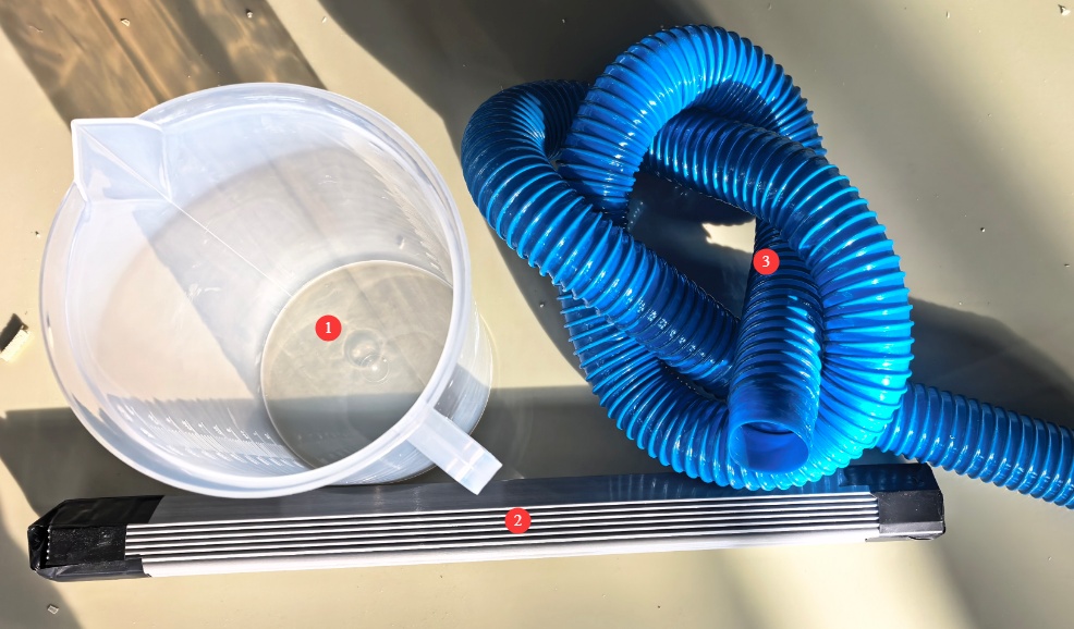
See Figure 1-1 for other major components.
| 数 | お願い |
|---|---|
| ① | メスシリンダー |
| ② | Sample Racks, V-Grooves, and O-Shaped Rods |
| ③ | 排気管 |
1.2.3 Downloading Electronic Documents
Links to the digital user manual, warranty card, calibration certificate, and other documents have been sent via email. If you did not receive the email, please contact us to obtain the links again.
2.安全上の注意
2.1 環境安全
2.1.1インストール要件
Ambient temperature: 5–25°C. Avoid excessively high temperatures, which can affect the stability of the test chamber’s temperature control, and excessively low temperatures, which can affect heating efficiency.
Relative humidity: ≤85% RH. The environment must be dry to prevent short circuits in the equipment’s electrical components caused by moisture.
Under standard atmospheric conditions, atmospheric pressure ranges from 86 to 106 kPa at altitudes between 0 and 2000 meters.
Other requirements: No direct sunlight; no strong electromagnetic fields (such as those from Voltage Transformers or large electric motors, to avoid interfering with the control system); no strong air currents (such as direct airflow from air conditioning vents).
2.1.2スペース要件
The equipment must be placed on a level surface; use a level to ensure the unit is stable.
Allow sufficient space around the equipment: ≥1500 mm on the left, right, and rear sides (to facilitate piping and cable connections, liquid refilling, and maintenance), and ≥2000 mm in front (to allow access to the control panel door and touchscreen).
2.2 電気安全
2.2.1 電源接続
Small models (SQ-150, SQ-250): 220 V single-phase power, power rating of 3.0 kW or less; requires a single 1.5 mm² wire;
Medium-sized model (SQ-750): 220 V single-phase power, 3.5 kW, requires a single 2.5 mm² wire;
Large models (SQ-010, SQ-016, SQ-020): 380V, three-phase, five-wire system; power rating greater than 5 kW; wiring requires a single 2.5 mm² conductor.
Power outlets must comply with safety standards, provide proper grounding, and have a rated current that matches the device’s power rating (it is recommended to install a dedicated circuit breaker).
2.2.2 Grounding Specifications
Grounding must be performed in accordance with standards, with a grounding resistance of ≤4 Ω. A dedicated grounding wire (with a cross-sectional area of at least 2.5 mm²) must be used to connect to the grounding electrode.
It is strictly prohibited to connect the ground wire to gas pipes, non-metallic water pipes, heating pipes, or other flammable or explosive facilities to avoid the risk of electric shock or fire.
2.3 Safety Precautions for the Use of Sulfur Dioxide
Throughout the entire procedure, you must wear a gas mask (SO₂-resistant), acid- and alkali-resistant gloves, and safety goggles. Direct contact with the test specimens after testing with bare hands is strictly prohibited.
Do not open the lid during the test run to prevent sulfur dioxide gas from escaping and causing respiratory irritation.
If you accidentally inhale sulfur dioxide and feel unwell, move to fresh air immediately; if symptoms are severe, seek medical attention promptly.
Check the air line seals regularly by applying soapy water to the joints to see if any bubbles form.
2.4 その他
For matters not covered in this manual, please proceed with caution or contact us.
3. Introduction to the Test Chamber
3.1 Front of the Test Chamber
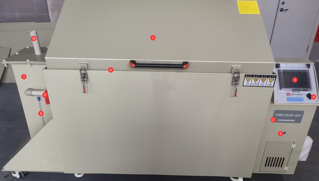
図3-1を参照してください。
| 数 | お願い |
|---|---|
| ① | 電源スイッチ |
| ② | Three-color indicator lights: yellow for standby, green for operation, and red for an alarm |
| ③ | タッチスクリーン |
| ④ | USB port, which can be used for future software updates |
| ⑤ | Test Chamber Lid |
| ⑥ | The test chamber lid has a groove with a soft gasket to ensure a tight seal; water can be added to ensure the chamber remains airtight. |
| ⑦ | Desulfurization tower, used for desulfurization after the test is complete |
| ⑧ | Desulfurization tower water level indicator: During operation, ensure that the water level remains at approximately two-thirds of the tower’s height. |
| ⑨ | The desulfurization pipe valve must remain closed during normal operation of the test chamber. When desulfurization is performed after the test is complete, this valve must be opened before starting the desulfurization process. |
| ⑩ | At the water inlet/vent of the desulfurization tower: Add water here when necessary; when desulfurization is required, connect the vent pipe to the outdoors. |
3.2 Rear of the Test Chamber
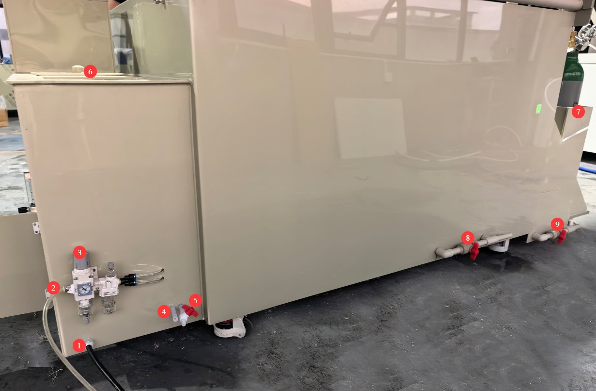
図3-2を参照してください。
| 数 | お願い |
|---|---|
| ① | Power cord—must be connected to a power source that matches the specifications on the nameplate |
| ② | Air compressor inlet; users must provide their own air compressor. When performing desulfurization, compressed air must be used to remove sulfur dioxide from inside the Sulfur Dioxide Test Machine. |
| ③ | For the air compressor inlet pressure regulating valve, pull it out and adjust the inlet pressure to 0.3 MPa. |
| ④ | Overflow outlet: Water may overflow while the test chamber is in operation; you can extend the hose to the drain. |
| ⑤ | Pure Water Tank Drain Valve: This valve should remain closed during normal operation of the test chamber; it should only be opened when it is necessary to drain the water from the pure water tank. A hose can be extended to the drain. |
| ⑥ | Pure water tank, used to automatically replenish the water in the heating water tank inside the test chamber; it is necessary to ensure that the pure water tank remains filled with water throughout the test. |
| ⑦ | Storage Area for Sulfur Dioxide Cylinders |
| ⑧ | Drain valve for the heated water tank inside the test chamber. This valve should remain closed during normal operation of the test chamber and should only be opened when it is necessary to drain the water from the heated water tank. A hose may be used to extend the drain outlet to a drain. |
| ⑨ | Desulfurization Tower Drain Valve: This valve should remain closed during normal operation of the test chamber and should only be opened when it is necessary to drain water from the desulfurization tower. A hose may be used to extend the drain outlet to a designated waste container. |
3.3 Left Side of the Test Chamber
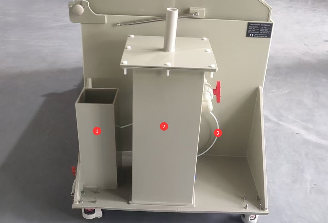
図3-3を参照してください。
| 数 | お願い |
|---|---|
| ① | Storage Area for Sulfur Dioxide Cylinders |
| ② | 脱硫塔 |
| ③ | The sulfur dioxide inlet tube is a PTFE tube with an inner diameter of 5 mm and an outer diameter of 7 mm, used to connect to the sulfur dioxide cylinder. |
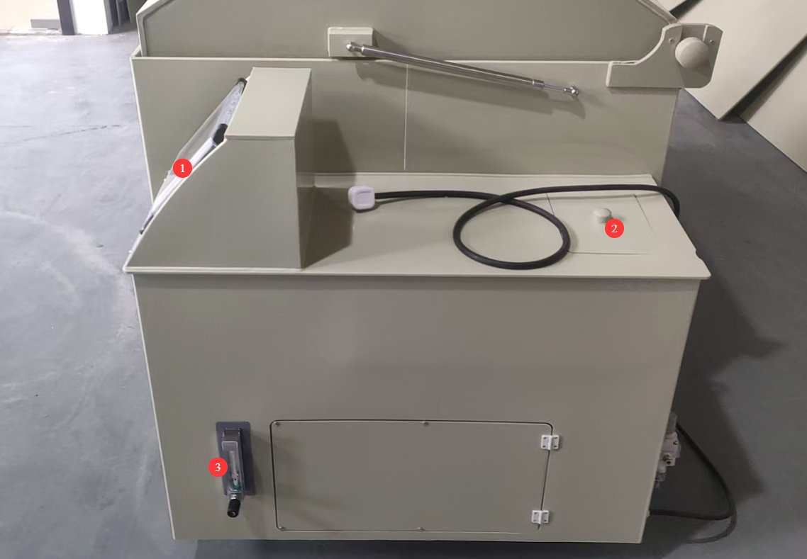
3.4 Right Side of the Test Chamber
図3および4を参照してください。
| 数 | お願い |
|---|---|
| ① | タッチスクリーン |
| ② | 純水タンク |
| ③ | Sulfur dioxide gas flow meter, measured in mL/min |
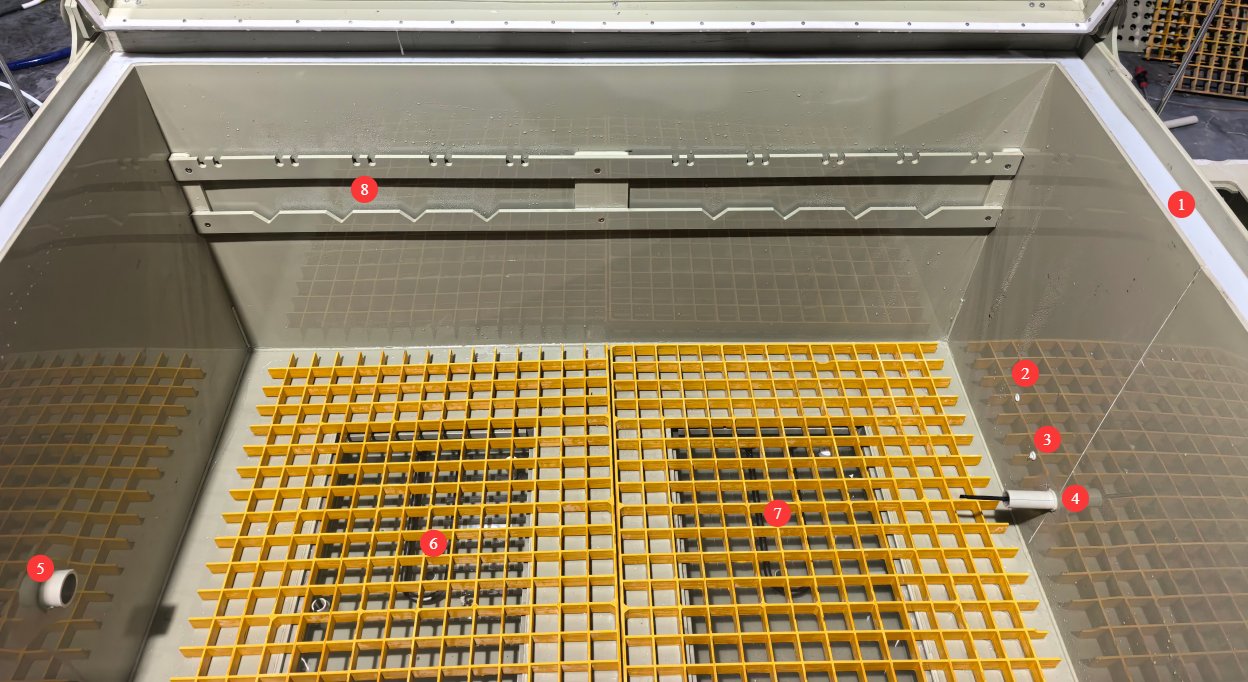
3.5 Inside the Test Chamber
See Figures 3–5.
| 数 | お願い |
|---|---|
| ① | Test Chamber Lid Groove |
| ② | Sulfur Dioxide Inlet |
| ③ | 圧縮空気入口 |
| ④ | 温度プローブ |
| ⑤ | Desulfurization Outlet |
| ⑥⑦ | Tray: During testing, samples can be placed directly on the tray. A heated water bath is located beneath the tray. |
| ⑧ | At the sample holder mounting point, samples can be suspended from the sample holder during testing. |
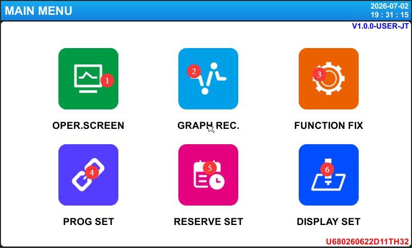
4. Introduction to the Touchscreen Program
4.1 メインインターフェイス
図4-1を参照してください。
| 数 | お願い |
|---|---|
| ① | 監視インターフェース |
| ② | Temperature Curve, used to view temperature curves |
| ③ | 機能設定 |
| ④ | Program Settings: For the sulfur dioxide test, only the calibration test is performed; the program settings function will not be covered here. |
| ⑤ | Appointment Settings |
| ⑥ | ディスプレイの設定 |
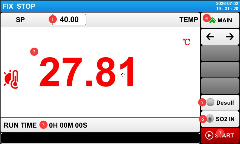
4.2 監視画面
図4-2を参照してください。
| 数 | お願い |
|---|---|
| ① | Test temperature setting: The standard requirement is 40°C. |
| ② | Real-time temperature display inside the test chamber |
| ③ | Test Duration Display |
| ④ | Return to the Main Screen |
| ⑤ | “Desulfurization” button: After the test is complete, click the “Desulfurization” button to remove sulfur. |
| ⑥ | Gas Inlet Button: Before starting the test, press the Gas Inlet button to allow sufficient sulfur dioxide gas to enter the test chamber. |
| ⑦ | Start/Stop Test; the test can be started once air intake is complete |
4.3 Function Settings Interface
図4-3を参照してください。
| 数 | お願い |
|---|---|
| ① | Test Mode Selection: Please select the Fixed-Value Mode |
| ② | Restart Procedures Following an Unexpected Power Outage. Stop: An operation that restores the system to a stopped state upon power restoration after a power outage during operation; Cold Start: An operation that restarts the test from the beginning upon power restoration after a power outage during operation; Hot Start: An operation that resumes operation from the point where it was interrupted before the power outage and restores the system to its pre-outage state upon power restoration. |
| ③ | Lock settings; once locked, the settings cannot be changed. |
| ④ | Password Setup: If you set a password, you will need to enter it the next time you access the settings menu. A value of 0 means no password is required. We recommend not setting a password. |
| ⑤ | Whether to return to room temperature after the test is complete: Since the test chamber does not have a cooling function, this option is not available. |
| ⑥ | The duration of sulfur dioxide injection should be calculated based on the test chamber volume (refer to the volume of the purchased test chamber), the required sulfur dioxide concentration (refer to the applicable standard), and the reading on the sulfur dioxide flow meter (typically 200 mL/min). |
| ⑦ | For the desulfurization duration, simply use the default setting of 10 minutes. |
| ⑧ | ページをめくる |
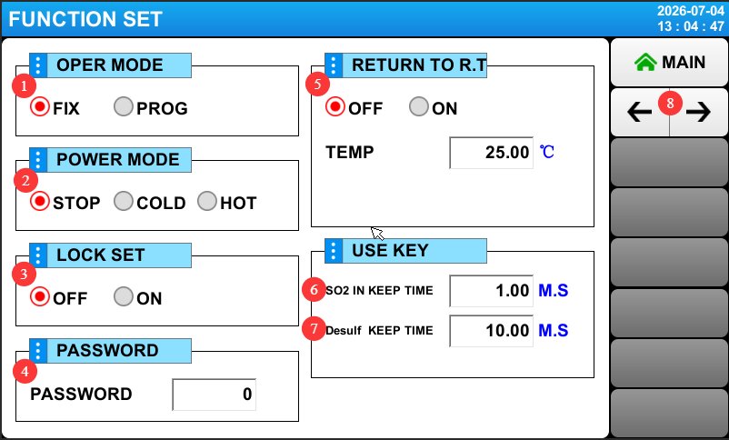
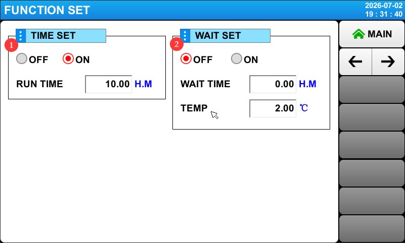
Click to go to the next page; see Figure 4-4.
| 数 | お願い |
|---|---|
| ① | Test Duration Settings. Select “ON” and set the test duration; the test chamber will automatically stop running once this duration is reached. Select “OFF,” and the test chamber will continue running until you manually click to stop the test. |
| ② | Wait for setup. Select “ON,” set the maximum wait time and temperature difference range, and click “Start Test.” The test duration will begin counting once the temperature inside the test chamber reaches the target value. Select “OFF,” and the test duration will begin counting immediately after clicking “Start Test.” |
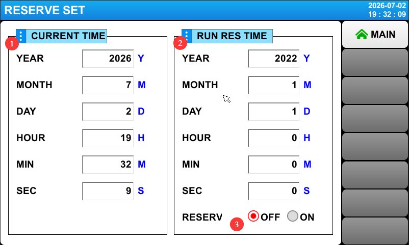
4.4 Appointment Settings Screen
See Figures 4–5.
| 数 | お願い |
|---|---|
| ① | The left column shows the current time |
| ② | You can enter your appointment time in the column on the right. |
| ③ | Scheduled Settings. Select “ON” and set the test chamber to standby mode; the test chamber will automatically start the test at the scheduled time. Select “OFF” to cancel the schedule. |
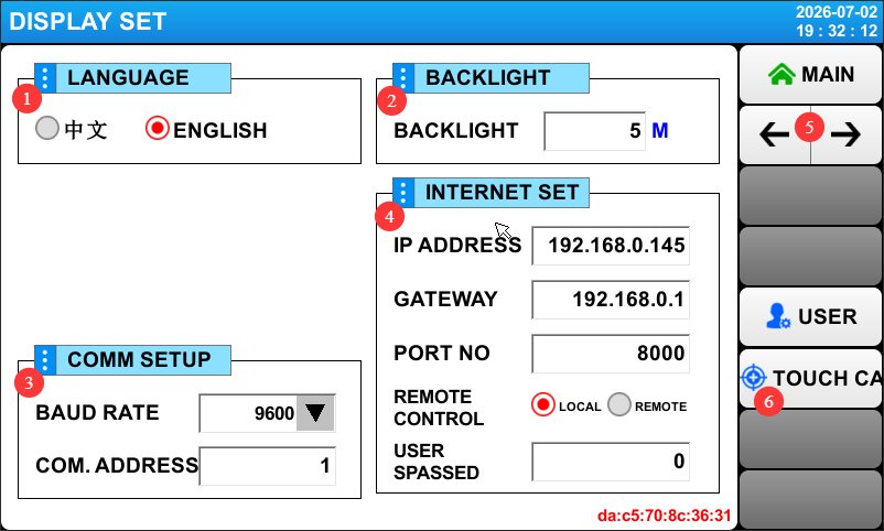
4.5 Display Settings Screen
See Figures 4–6.
| 数 | お願い |
|---|---|
| ① | Switch Display Language |
| ② | Touchscreen Backlight Duration Settings |
| ③④ | The test chamber does not currently have communication capabilities, so no settings need to be configured or modified. |
| ⑤ | Turn the page to view the historical alarm records |
| ⑥ | Touchscreen Calibration: If the touchscreen’s tap location does not match the actual location, follow the instructions to recalibrate the touchscreen. |
5. Operating Procedures For The Sulfur Dioxide Test Machine
5.1 Cleaning the Test Chamber
Before using the test chamber for the first time or after a long period of inactivity, clean the interior of the test chamber and the purified water tank.
5.2 水を加える
| Where to Add Water | お願い |
|---|---|
| 純水タンク | Add purified water; the purified water will automatically flow from the purified water tank into the heating water tank inside the test chamber. To ensure the test duration, fill the purified water tank to capacity. |
| 脱硫塔 | Add purified water until it reaches about two-thirds of the height. |
| Test Chamber Lid Groove | Water may be added to ensure that the test chamber is completely sealed when the lid is closed. |
5.3 Connecting Auxiliary Equipment
| デバイスを接続する | お願い |
|---|---|
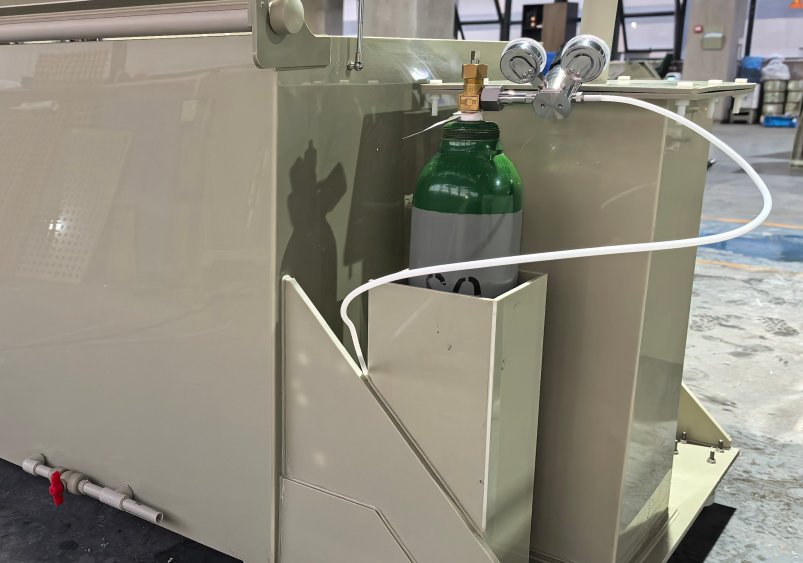
| Sulfur Dioxide Cylinders | See Figure 5-1. Connect the intake pipe. |
| エアコンプレッサ | Refer to Section 3.2, connect the intake pipe, and adjust the intake pressure to 0.3 MPa. Apply soapy water to all joints and valves, and let them sit for 5 minutes; proceed to the next step only if there are no bubbles and no air leaks. |
5.4 Placing the Sample
Refer to Section 3.5. After placing the sample, close the test chamber lid.
5.5 Sulfur Dioxide Test Procedure
5.5.1 General Operating Procedures
| ステップ | お願い |
|---|---|
| ① Test Parameter Settings | Refer to Chapter 4 to configure all test parameters, such as: test temperature, fixed test duration, wait function, sulfur dioxide injection duration, and desulfurization duration. |
| ② Sulfur Dioxide Feed | Set the sulfur dioxide air compressor pressure reducer to 0.2 MPa (see Section 4.2), press the gas inlet button (see Section 3.4), adjust the flowmeter to 200 mL/min. Apply soapy water to all fittings and valves to ensure there are no bubbles or air leaks. You may either wait for the gas flow to stop automatically at the end of the flow duration or press the “Gas In” button again to stop the gas flow. After stopping the gas flow, close the main valve on the sulfur dioxide cylinder. |
| ③ Start-up Test | Click START to begin the test. If a wait time has been set, the test duration will begin once the test chamber has reached the target temperature; if no wait time has been set, the test duration will begin immediately after the test is started. |
| ④ Monitoring the Test Process | Ensure that the test chamber temperature can reach the target temperature; ensure that the purified water tank is always filled with water. If the water level in the heating water tank is too low, the test chamber will sound an alarm and pause the test. Once water is added to the purified water tank, the test chamber will clear the alarm and automatically resume the test. |
| ⑤ Stop the test | Once the test duration reaches the set time, the test chamber automatically stops the test; users can also click STOP to manually stop the test. |
| ⑥ Desulfurization | Refer to Section 3.1 to open the desulfurization line valve, then refer to Section 4.2 and click the “Desulfurization” button to begin desulfurization. The desulfurization process will automatically stop once the set duration has elapsed; the user may also click the “Desulfurization” button again to stop the process. After desulfurization is complete, close the desulfurization line valve. |
5.5.2 Long-Term Test Procedures
For extended tests lasting several days: It is recommended to vent and ventilate the system once daily and replenish it with fresh sulfur dioxide to maintain a stable concentration. Follow the procedures for desulfurization and sulfur dioxide injection described in Section 5.5.1 when ventilating the system.
Check the water level in the purified water tank daily and replenish any water lost through evaporation promptly.
5.6 Remove the specimen
After confirming that the desulfurization process is complete, slowly open the lid a crack to check for any pungent odors escaping.
Put on protective gloves and safety goggles, then fully open the lid of the box.
Use a tool to remove the sample and let it sit in a well-ventilated area.
Do not examine the surface of the specimen at close range immediately; wait until the residual gas has dissipated before conducting the evaluation.
Conduct corrosion rating assessments or performance tests on the test specimens in accordance with the applicable test standards.
5.7 試験後の手順
5.7.1 Cleaning and Storing the Test Chamber
After the chamber has cooled, rinse the inner walls of the chamber and the test specimen rack with clean water to remove any residual corrosion; open the drain valve on the heating water tank to drain the wastewater from the bottom of the tank; wipe the chamber lid and the sealing surface around the chamber opening with a dry cloth; turn off the power to the test chamber and the air compressor.
5.7.2 Environmentally Sound Treatment of Waste Liquids
The absorption solution in the desulfurization tower is acidic and must be replaced after one week of continuous use. Open the desulfurization tower’s drain valve to discharge it into a designated waste liquid container; the waste liquid must be neutralized with an alkaline solution (sodium hydroxide or lime water) to a pH of 6–9 before discharge; it is strictly prohibited to pour acidic wastewater directly into the sewer system.
Safety Guidelines for Neutralization: Wear acid- and alkali-resistant gloves and safety goggles; slowly pour the alkaline solution into the acidic waste liquid while stirring and monitoring the pH to prevent splashes and chemical burns.
6. Daily Maintenance and Care of the Test Chamber
6.1 定期点検項目
The following checks should be performed before and after each test: Check the gas line connections for looseness or leaks; check the interior and exterior of the tank for cracks or damage; check that all valves are in the correct position; and confirm that the water levels in the desulfurization tower and the purified water tank are normal.
6.2 定期メンテナンス計画
6.2.1 Weekly Maintenance Tasks
Replace the absorption water in the desulfurization tower to maintain absorption efficiency; replace the water in the heating tank of the test chamber to keep the water clean; Clean the water trough on the test chamber lid to prevent scale buildup; check the gas cylinder pressure to ensure sufficient gas supply; if the remaining pressure on the gas cylinder pressure gauge falls below 0.5 MPa, stop the test and replace the sulfur dioxide cylinder with a new one.
6.3 長期保管およびメンテナンス
When the equipment will not be used for an extended period, drain all standing water from the pipes; thoroughly clean the interior and exterior of the unit, allow it to air dry, and then close the lid; disconnect the power supply and cover the unit with a dust cover; store it in a dry, well-ventilated environment at a temperature between 0°C and 40°C; power on the unit once a month for 30 minutes to remove moisture.
6.4 Calibration Interval Requirements
To ensure the measurement accuracy and operational reliability of the test chamber, it is recommended that it be sent periodically to a qualified third-party metrology organization for calibration. The recommended calibration interval is 12 months. Users may determine the specific calibration interval based on frequency of use, environmental conditions, and quality system requirements.
7. Troubleshooting and Resolving Common Problems
| 障害症状 | 考えられる原因 | 手順 |
|---|---|---|
| When sulfur dioxide is introduced, the flow meter shows no reading when adjusted. | The sulfur dioxide cylinder is underpressurized, and the pressure-reducing valve is not open. | See Section 6.2.1 to check the cylinder pressure; see Section 5.5.1 to check the cylinder pressure regulator. |
| The touchscreen displays a low-water warning | Low Water Level in the Heating Tank | Refill the purified water tank with purified water |
| The temperature does not rise or rises slowly | Heating Element Failure | 発熱体の交換 |
| Temperature Out of Control—Overheating | Solid-State Relay Breakdown | Replacing a Solid-State Relay |
| There has been a sulfur dioxide gas leak, and a pungent odor is emanating. | Air leaks at fittings, valves, and test chamber lids | Use soapy water to check for air leaks at the joints and valves; ensure the test chamber lid remains airtight; water may be added to the lid groove to create a seal. |