
 英語
英語 中文简体
中文简体 Русский
 Español
 Português
 Türkçe
 العربية
 Deutsch
 Polski
 Italiano
 Français
 한국어
한국어 ไทย
ไทย Tiếng Việt
 日本語
日本語





























Capacitive Coupling Clamp
ユーザーズマニュアル
適用 LISUN モデル: VFTC
1. 機器の基本的な理解
1.1 製品概要
1.1.1 VFTC CCC Capacitively Coupled Clamp
その VFTC CCC Capacitive Coupling Clamp (CCC ) was developed in accordance with ISO 7637-XNUMX-3:2016 andGB/T 21437.3-2021, is designed to apply fast electrical transient pulse disturbances to signal lines, control lines, and communication harnesses (excluding power lines) of in-vehicle electronic devices to perform transient coupling immunity tests.
The device injects transient pulses into the harness under test via capacitive coupling, eliminating the need for direct electrical connection to signal wires. It is suitable for testing multiple harnesses simultaneously and is widely used for EMC immunity verification, R& D testing, mass production quality inspection, and third-party laboratory certification testing of automotive components such as ECUs, sensors, BMS, OBCs, and in-vehicle radar, among other automotive components, for EMC immunity verification, R& D testing, mass production quality inspection, and third-party laboratory certification testing.
Note: The CCC (capacitively coupled clamp) is only intended for fast transient pulses 3a and 3b; it must not be used for slow transient pulses such as 2a. For slow pulses, please use the DCC or ICC coupling methods.
1.1.2 Description of Key Auxiliary Equipment
その VFTC CCC capacitively coupled clamp must be used in conjunction with the LISUN EMS-ISO7637 Automotive Transient Immunity Generator, which is used to generate fast transient pulses 3a and 3b.
For information on using the EMS-ISO7637, please refer to its operating instructions.
1.2 主な技術仕様
| プロジェクト | 技術仕様 |
|---|---|
| カップリングコンデンサ | 100 pFのに200 pFの |
| Maximum Pulse Voltage Rating | 5000 V (peak) |
| Standard Coupling Harness Length | 1000 mm (1 m, required by standard) |
1.3 Applicable Standards, Terms, and Test Subjects
1.3.1 適用規格
GB/T 21437.3–2021″Road Vehicles—Test Methods for Electromagnetic Disturbances on Electrical and Electronic Components Caused by Conduction and Coupling—Part 3: Immunity to Electrical Transients Coupled to Non-Power Lines,” corresponding to the Capacitive Coupling Clamp (CCC) method in Section 4.5.
ISO 7637-3:2016 Road vehicles—Electrical disturbances from conduction and coupling—Part 3, corresponding to Section 4.5 (CCC 方法)。
1.3.2 Applicable DUT (Device Under Test) Types
Passenger cars, commercial vehicle ECUs, various sensors, and actuators; new energy vehicle BMS (Battery Management Systems), OBC (On-Board Chargers), and DC-DC converters; in-vehicle displays, radar, gateways, and electronic components related to CAN/LIN buses.
Note: The test subject is a non-power harness (signal, control, and communication wires); the DUT’s main power supply cable must not pass through the CCC coupling clamp.
2.使用上の注意
2.1 Safety Precautions for Personnel
The CCC coupling clamp can withstand a maximum pulse voltage of 5000 V. During testing, do not touch the metal housing of the coupling clamp, the coaxial connector, or the bare conductors of the wire harness under test to prevent high-voltage electric shock;
Equipment connections, wiring harness routing, and wiring adjustments must be performed with the pulse generator turned off and the main unit powered down;
Operators must complete basic training in automotive EMC testing and be familiar with the risks associated with high-voltage pulse testing; metal objects must not be placed on the test bench without authorization to prevent high-voltage coupling and interference with test results.
2.2 機器の安全性
Do not exceed the maximum pulse voltage input of 5000 V; exceeding this voltage will cause the internal capacitors of the coupling clamp to break down and fail;
The input interface may only be connected to the BNC output port of the EMS-ISO7637 pulse generator; connecting it to mains power or a DC power source is prohibited;
The hinged top cover of the coupling clamp must be fully closed, leveled, and locked before starting the test. If the top cover is not closed, it will alter the coupling parameters, rendering the test results invalid and increasing the risk of high-voltage hazards.
2.3 テスト環境の要件
周囲温度: 23°C±5°C; ambient humidity: 30%–70% RH, no condensation; do not power on the device for testing in humid environments;
A grounding plate must be provided (copper or galvanized steel plate, thickness ≥ 0.5 mm, area ≥ 1 m × 1 m, reliably connected to the protective ground); the housing of the CCC coupling clamp must be reliably connected to the grounding plate;
Keep away from environments with strong vibrations, corrosive gases, or heavy dust;
DUT Power Supply Conditions: 13±1 V for 12 V systems; 26±2 V for 24 V systems. Set the DUT operating voltage in accordance with the standard.
3. Equipment Overview and Wiring
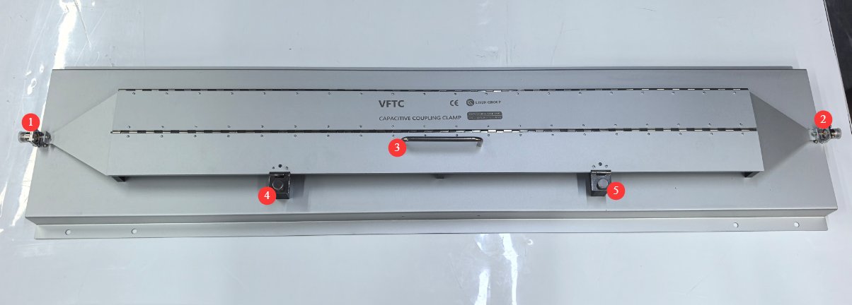
3.1 装備の外観
図3-1を参照してください。
| 数 | お願い |
|---|---|
| ①② | Type N connector |
| ③ | Hinged Top Cover |
| ④⑤ | 固定ネジ |
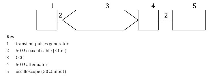
3.2 Schematic Diagram of Waveform Verification Connection
See Figure 3-2 (taken from ISO 7637-3, Figure 1).
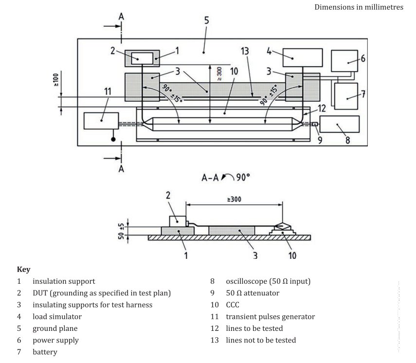
3.3 CCC Capacitively Coupled Clamp Test Connection Diagram
3.3.1 Standard Diagram
See Figure 3-3 (taken from ISO 7637-3, Figure 2).
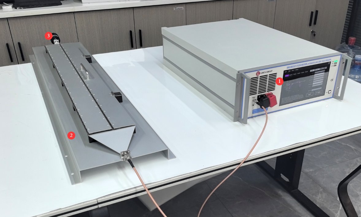
3.3.2 Product Connection Diagram
See Figures 3–4.
| 数 | お願い |
|---|---|
| ① | EMS-ISO 7637 Automotive Transient Immunity Generator |
| ② | VFTC CCC Capacitive-Coupled Clamp |
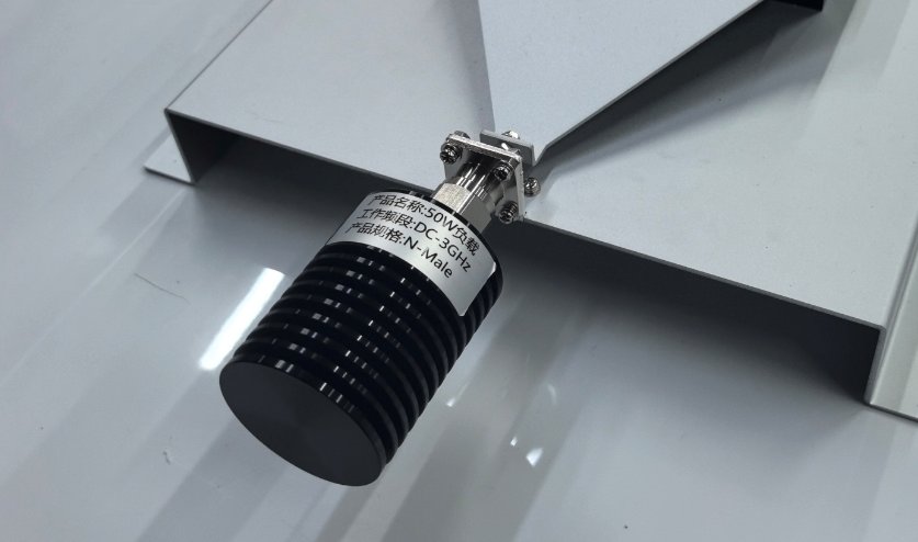
| ③ | 50 Ω load; see Figure 3-5. If you do not need to monitor the test waveform, you can simply replace the 50 Ω attenuator (item 9) and the oscilloscope (item 8) shown in Figure 3-3 with the 50 Ω load included as standard with the LISUN. |
| Note: For the connection and layout of the DUT, refer to Section 3.2.1. | |
4. CCC Capacitively Coupled Clamp Test
Waveform Verification
| 説明書 | お願い |
|---|---|
| ① | Refer to Figure 3-2: The interior of the CCC coupling chamber remains empty; the EMS-ISO7637 is connected to the CCC’s N input port via a 50-Ω coaxial cable; the CCC’s N output port is connected to a 50-Ω attenuator and an oscilloscope with a 50-Ω input impedance. |
| ② | EMS-ISO7637 touchscreen interface, select “Pulse3a” for the pulse type, select “CCC” for the coupling mode, and run the test. Read the oscilloscope waveform to verify that the pulse parameters are correct: rise time 5 ns ± 1.5 ns, pulse width 150 ns ± 45 ns, output voltage error ±5%. |
| ③ | ソフトウェア設定ページで、下図のように EMS-ISO7637 touchscreen interface, switch to the Pulse3b coupling mode and select “CCC.” Repeat the test and verify that the pulse parameters are correct. |
| ④ | After the parameters have been verified as acceptable, shut down the EMS-ISO7637. |
| ⑤ | After completing the waveform verification, connect the DUT as described in Section 3.3 and prepare for the formal test. |
DUT Pre-Operation Check
Power on the DUT and ensure it operates normally in the operating mode specified in the test plan; all DUT functions must be normal, with no error messages. If the DUT exhibits abnormal behavior immediately upon power-up, check the wiring; proceed to the immunity test only after the DUT has returned to normal operation.
Startup Test
4.3.1 Pulse 3a Forward Fast Transient Test
Ensure that the CCC cover is fully closed, the wiring harness is laid flat, and personnel are kept away from high-voltage areas;
EMS-ISO7637 touchscreen interface, select “Pulse3a,” choose “CCC” as the coupling mode, and run the test to begin applying the Pulse3a interference;
Continuously monitor the DUT’s status throughout the test and record any changes in functionality, fault codes, temporary failures, system crashes, and other such phenomena.
4.3.2 Pulse 3b Negative Fast Transient Test
Verify that the hardware wiring and harness layout remain unchanged;
EMS-ISO7637 touchscreen interface, select “Pulse3b,” choose “CCC” as the coupling mode, and run the test to begin applying Pulse3b interference;
Continuously monitor the DUT’s status throughout the test and record any changes in functionality, fault codes, temporary failures, system crashes, and other such phenomena.
4.3.3 Rotational Testing of Multiple Harness Sets
If the total number of DUT signal lines exceeds the number that can fit into a single set of coupling clamps, testing must be performed in groups:
The pulse generator stops outputting pulses, and the equipment is powered off; replace the test harness with another set, lay it flat inside the CCC coupling clamp, and close the top cover; repeat steps 4.3.1 and 4.3.2 to complete the 3a and 3b pulse tests for this set of harnesses; testing is complete for all harness groups.
4.4 DUT Pass/Fail Criteria (FPSC—Functional Performance Status Classification)
| レベル | Equipment Status Description | Determination Result |
|---|---|---|
| 甲種 | All functions operated normally throughout the entire test; there were no abnormalities and no data errors. | Passed (with the highest score) |
| グレードB | During testing, temporary performance degradation and brief functional failures occurred; after the interference was removed, the DUT automatically returned to normal operation with no stored error codes and no hardware damage. | Acceptable (allowed by most automakers) |
| グレードC | The hardware is not damaged, but the device must be powered off and restarted for functionality to be restored; or an error code appears that cannot be cleared. | 失敗する |
| グレードD | Physical damage to the hardware; components burned out | 失敗する |
5. Daily Maintenance and Care of Equipment
5.1 Daily Use and Maintenance (After Each Test)
After the test is complete, turn off the power to the EMS-ISO7637 and disconnect the coaxial cable;
Use a dry, lint-free soft cloth to wipe down the coupling clamp housing and top cover to remove debris and dust from the wiring harness; do not use liquids to clean directly;
Inspect the N-type coaxial connector and use a lint-free brush to remove any dust from the connector. Do not scrape the inner core of the connector with any hard objects;
Close the hinged top cover and store the equipment inside a dry, dust-proof cover;
Store cables in coils; do not bend coaxial RF cables at sharp angles to prevent internal damage.
5.2 定期メンテナンス
Monthly: Check that the ground wire is secure; check the hinge screws on the top cover for looseness and tighten any loose screws;
Annual Calibration: To ensure the measurement accuracy and operational reliability of the equipment, it is recommended that it be sent periodically to a qualified third-party metrology laboratory for calibration. The recommended calibration interval is 12 months. The specific calibration interval may be determined by the user based on frequency of use, environmental conditions, and quality system requirements.
5.3 保管および輸送の要件
Storage Conditions: Temperature: −10 to +50 °C; Humidity: 30–70% RH; Avoid direct sunlight and corrosive gases;
Ensure proper cushioning and protection during transport; avoid dropping or bumping the product, and protect the N-type connector.
6.よくある問題のトラブルシューティングと解決
| 障害の症状 | トラブルシューティングと解決 |
|---|---|
| その EMS-ISO7637 Pulse Generator is reporting an output overload alarm | With the power off, inspect the N-connector; check the coaxial cable for any crushing or damage, and ensure there is no short circuit between the connector and the coaxial cable; inspect the wiring harness to ensure the cable jacket is intact and that no bare metal wires are touching the metal housing of the coupling clamp; |
| Poor test repeatability | During each test, ensure that the top cover is completely flat and securely fastened; lay the wiring harness in a single layer, strictly adhering to a 1-meter coupling length; shorten the grounding cable to ensure reliable protective grounding via the grounding plate; check whether the DUT’s DC power supply output is stable. |
| The CCC coupling clamp housing causes a tingling sensation (like an electric shock) | Stop the test immediately; check the grounding connections to ensure a reliable, low-impedance connection between the grounding rod and the grounding plate, and connect the grounding plate to the laboratory’s protective ground. |