
 英語
英語 中文简体
中文简体 Русский
 Español
 Português
 Türkçe
 العربية
 Deutsch
 Polski
 Italiano
 Français
 한국어
한국어 ไทย
ไทย Tiếng Việt
 日本語
日本語





























AC / DCハイポットテスター
ユーザーズマニュアル
適用 LISUN モデル: WB2681A
1. 開封とデバイスの基本的な操作方法
1.1 主な技術仕様
| 技術パラメータ | お願い |
| 絶縁電圧 | DC 250 V, DC 500 V, DC 1000 V (three settings available) |
| Turn-on Voltage Range | ±10% @ rated voltage |
| 絶縁抵抗 | 0~1999 MΩ |
| 試験時間 | 1–99 seconds or manual control |
1.2 開封と付属品の確認
1.2.1 開梱と目視検査
When unpacking the device, handle it gently to avoid scratching the exterior casing with sharp tools. After unpacking, first inspect the exterior of the device to ensure there is no visible deformation or dents, and that the buttons are not damaged or loose. If you notice any abnormalities with the device or its accessories, do not turn it on. Please contact us immediately.
1.2.2 本体および付属品
ホスト: 1 WB2681A ホスト。
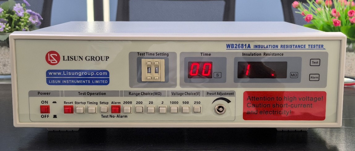
図1
主な構成要素は以下のとおりです。
| 数 | お願い |
| ① | 電源コード |
| ② | Test Object Connection Cable |
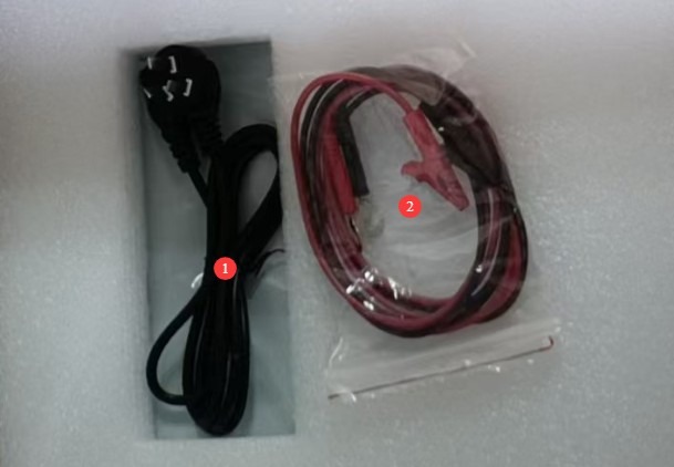
図2
デジタル版ユーザーマニュアル、ソフトウェア、保証書、その他の資料のダウンロードリンクをメールでお送りしました。できるだけ早くダウンロードしてください。メールが届いていない場合は、ご連絡いただければダウンロードリンクを再送いたします。
2.安全上の注意
2.1 電気安全
2.1.1 電源要件
Use a single-phase AC 220V ±10%, 50/60 Hz three-prong outlet; the ground prong must be connected to earth.
2.1.2 接地要件
The instrument ground wire is reliably connected to the protective grounding conductor, and the protective grounding resistance is ≤4 Ω;
Do not short-circuit the output terminals to the AC power source to prevent the housing from becoming energized.
2.2 環境安全
2.2.1 温度および湿度の要件
Avoid using the device in environments where humidity exceeds 70% (without condensation) or temperatures fall outside the range of 0–35°C. The optimal operating temperature is 25±2°C.
2.2.2 環境的禁忌
強い磁場と強い電場が存在する環境。
腐食性ガスまたは液体を含む環境。
Areas with flammable and explosive dust or hazardous materials;
粉塵が多く、高温多湿で、直射日光が当たる環境。
2.3操作上の安全性
The test circuit of the equipment can generate an output voltage of up to 1000 V DC. Once testing begins, do not touch the test circuit, the device under test, or the metal ends of the test leads with your hands. Do not short-circuit the test leads to prevent high-voltage electric shock;
It is strictly prohibited to perform insulation resistance tests on live circuits, equipment, or components; before testing, ensure that the test subject is completely de-energized and has been properly discharged;
試験片はゴム製の絶縁マットの上に置く必要があります。
作業員はゴム製の絶縁手袋を着用しなければならない。
作業者は手を乾いた状態にし、金属製の装身具を身につけてはならない。感電事故を防ぐため、試験中は飲食を禁止する。
試験対象物を交換する前に、まず試験を停止し、デバイスの出力電圧が0であることを確認する必要があります。
When multiple people are involved, clearly define roles and responsibilities, and confirm with each other before starting the test to avoid errors.
2.4その他
本マニュアルに記載されていない事項については、慎重に進めるか、弊社までお問い合わせください。
3. 機器の概要と配線
3.1 機器前面パネルの概要
| 数 | お願い |
| ① | 電源スイッチ |
| ② | Test time setting: two-digit dial code; test times can be set from 1 to 99 seconds; used in conjunction with a timer switch |
| ③ | Test time display, in seconds. Note: Available only when the timer switch is enabled. |
| ④ | “The insulation resistance display shows the insulation resistance value of the test object during testing and the lower limit of the alarm resistance during setup. If the selected range is too small, an overflow indicator ‘1’ appears. If ‘1’ is still displayed at the maximum range, it indicates that the test object is open-circuited or that its resistance exceeds the device’s measurement range.” |
| ⑤ | Test Status Indicator: Test: Testing in progress; Alarm: Insulation resistance below threshold + buzzer alarm (long beep) |
| ⑥ | Reset button: Press to clear the alarm, end the test, and return the device to standby mode. |
| ⑦ | テストを開始するにはスタートボタンを押してください。テストランプが点灯します。 |
| ⑧ | Timer switch: Press to enable the timer; release to disable the timer. |
| ⑨ | Preset/Test Switch: Press to enter Preset mode and set the lower limit of the alarm resistance; push out to enter Test mode, where you can perform a formal test. |
| ⑩ | Alarm button: Press to enable the alarm (an alarm sounds when the insulation resistance falls below the lower limit); release to disable the alarm. |
| ⑪ | Range selection button, with four selectable ranges: 2 MΩ, 20 MΩ, 200 MΩ, and 2000 MΩ |
| ⑫ | Test voltage selection button: Three settings available—DC 250 V, 500 V, and 1000 V |
| ⑬ | Resistance Threshold Adjustment Knob: In the default setting, this knob adjusts the lower limit of the alarm resistance, in MΩ. |
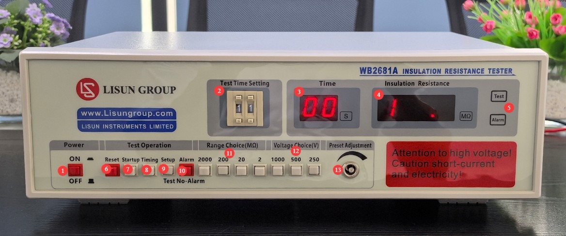
図3
3.2 機器背面パネルの概要
| 数 | お願い |
| ① | Power cord receptacle, with built-in fuse |
| ② | Connect the test leads to the resistor under test: use the red lead to connect to the high-voltage end of the device, and use the black lead to connect to the low-voltage end or ground of the device. |
| ③ | Ground terminal; connect to the shielding layer of the device under test (if any) |
| ④ | PLC output interface (expanded functionality) allows the device to be integrated with other equipment to form an interlocked system. “Start” and “Reset” are external passive normally open contact inputs, while “Test” and “Alarm” are passive normally open contact outputs from the device. |
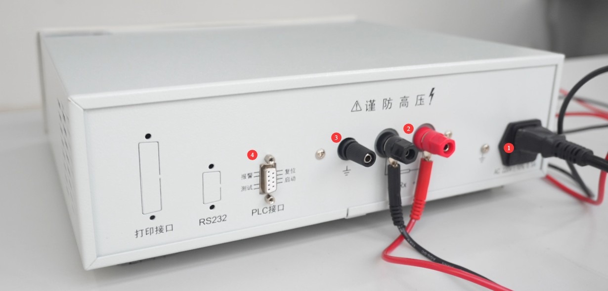
図4
4.試験前の準備
4.1 Equipment Warm-up
Turn on the device. At this point, the insulation resistance display window will show the overflow indicator “1,” and the test time display window will show “00.” Allow the device to warm up under no-load conditions for 15 minutes before proceeding with subsequent operations to ensure that the internal components are operating stably.
4.2 試験片の準備
4.2.1 Power Interruption and Discharge
Ensure that the power supply to the device under test is completely disconnected. For devices under test that contain energy-storage components such as capacitors and inductors, perform a thorough short-circuit discharge to prevent residual voltage from damaging the equipment or causing electric shock.
4.2.2 Surface Cleaning and Treatment
Wipe away any dust, oil, or water from the test area of the test object to ensure that its surface is dry and clean. This prevents surface contaminants from causing low insulation resistance readings, which could lead to incorrect results.
4.2.3 Connecting the Test Object
Identify the high-voltage end and low-voltage end/ground end of the device under test, and determine whether there are any polarity requirements for the connections; check that the device under test has no physical damage or broken wires and is in a normal, ready-to-test condition; make the connections as described in Section 3.2.
5。 試験手順
5.1 Basic Test Parameter Settings
5.1.1 Selection of Test Voltage
Based on the type of test object and the standard requirements (see Appendix), press the test voltage selection button on the front panel to select the appropriate setting for 250 V, 500 V, or 1000 V DC, ensuring that the voltage setting matches the requirements for the test object.
5.1.2 Selection of Measurement Range
Based on the estimated insulation resistance value of the test object, press the range selection button on the front panel to select the appropriate range (2 MΩ, 20 MΩ, 200 MΩ, or 2000 MΩ). If no estimated value is available, select the highest range first, then adjust it based on the test results.
5.2 Setting the Lower Limit for the Alarm Resistance (Optional)
Press the Preset/Test switch on the front panel. The device will then enter the alarm value setting mode, and the insulation resistance display window will show the set value.
Press the start button; the test indicator light will turn on, simulating the test condition. Use a small screwdriver to slowly adjust the resistance threshold knob and observe the changes in the value displayed in the insulation resistance window until the displayed value matches the lower limit of the alarm resistance specified by the standard or test requirements.
After calibration is complete, press the Reset button to pop up the Preset/Test switch, and the device will return to test standby mode; press the Alarm button to enable the alarm function.
5.3 Timed Test Parameter Settings (Optional)
Press the timer switch on the front panel to enter timed test mode; the test time display window will enter the set value state.
Turn the test time setting DIP switch (two-position) to set the test duration to a value between 1 and 99 seconds, as required by the standard or test specifications. Observe the value displayed in the test time window to confirm that it matches the set value.
If scheduled testing is not required, simply keep the timer switch in the “on” position; the test duration can then be controlled manually.
5.4 起動テスト
Press the Start button on the front panel; the test indicator light will illuminate, high voltage will be output from the device’s test terminal, and the device will officially enter test mode:
Timed Mode: The test time display window begins a countdown, and the insulation resistance display window shows the insulation resistance value of the test object in real time; Manual Mode: The test time display window remains at “00,” and the insulation resistance display window shows the insulation resistance value of the test object in real time.
Warning: Do not touch the test object, test leads, or equipment terminals during testing to prevent electric shock from high voltage.
5.5 Ending the Test
5.5.1 Manual Reset Termination
Whether in timed or manual mode, if you need to terminate the test early, press the reset button on the front panel. The test indicator light will turn off, the high-voltage output will stop, the device will return to standby mode, and any alarms (if present) will be cleared simultaneously.
5.5.2 Automatic Alarm Termination
If the alarm function is enabled, when the insulation resistance of the test object falls below the preset lower limit, the alarm indicator light will illuminate, the device will emit a long audible alarm, and the test will automatically terminate while the high-voltage output stops.
5.5.3 Automatic Termination Upon Timer Expiration
In timed test mode, when the test timer counts down to “00,” the device automatically terminates the test, the test indicator turns off, and the high-voltage output stops. If the insulation resistance of the test object meets the requirements, no alarm will sound.
5.6 テスト結果の解釈
5.6.1 Determination of Conformity
Throughout the entire test, if the value displayed in the insulation resistance window remains stable and the insulation resistance of the test object is ≥ the standard requirement or the set lower alarm limit, the test object is deemed to have passed.
5.6.2 Determination of Nonconformity
During testing, if the device triggers an alarm, the alarm indicator lights up, and the value displayed in the insulation resistance window is less than the set lower alarm limit, the test result is deemed unsatisfactory.
5.6.3 Determining Abnormalities in Range/Voltage Settings
After the test begins, the device emits an intermittent beep. The value displayed in the insulation resistance window is invalid, indicating a mismatch between the voltage range and the measurement range. Reset the device, adjust the ranges according to the standard requirements, and then retest;
After the test starts, if the insulation resistance display window shows the overflow indicator “1,” it means the range selected is too small. Reset the device, select a higher range, and retest.
6. 機器の日常的なメンテナンスと手入れ
6.1。XNUMX日常のメンテナンス
Before turning on the power, inspect the equipment to ensure it is clean and undamaged, that the cables show no signs of aging or breakage, and that the connectors are secure; Check that the test object’s connecting cables are free of oxidation or burn marks; if any are present, wipe them with a specialized contact cleaner, and contact us to replace parts if necessary; after testing is complete, disconnect the power and wipe the device’s surface and the test area with an antistatic, dry cloth.
6.2 長期保管
長期間使用しない場合は、湿気や直射日光を避け、乾燥した風通しの良い場所に保管してください。すべてのケーブルを外し、付属品は別々に保管し、本体を防塵布で覆ってください。内部の電子部品の劣化を防ぐため、毎月30分間電源を入れてください。
7.よくある問題のトラブルシューティングと解決
| 障害症状 | 考えられる原因 | 手順 |
| デバイスの電源が入りません | 電源コードがしっかり差し込まれていません。ヒューズが切れています。 | Check the power cord connections; check the fuse in the device’s power input port. If it is blown, replace it with a 5A fuse of the same model. |
| After turning on the computer, the screen flickers and the keys don’t respond. | 不安定な電源電圧 | Use a multimeter to measure the supply voltage and verify that it falls within the range of AC 220 V ± 10%. If the voltage is unstable, install a voltage regulator. |
| After the test starts, the device emits an intermittent beep. | The range setting is too high | Please reset the device, select a lower gear, and try again. |
| After the test started, the insulation resistance display window showed the overflow indicator “1.” | The selected range is too small | Reset the device, then select the high range and retest. If “1” is still displayed when the maximum range is selected, this indicates that the test circuit is open or that the resistance of the device under test is too high. |
| The values in the display window are fluctuating erratically | The operating environment may be subject to interference from strong magnetic fields or strong electric fields. | Keep away from environments with strong magnetic fields or strong electric fields. |
| Test results do not match the alarm status (test results are normal but an alarm is triggered; test results are abnormal but no alarm is triggered) | Incorrect sequence of operations for selecting the measurement range and setting thresholds | Please refer to Chapter 5. Be sure to select the measurement range before setting the threshold; otherwise, the threshold values will be unavailable. |
Appendix A: Insulation Resistance Test Requirements in Relevant Standards
| 標準番号 | By Type of Electronic Product/System | Recommended Test Voltage (DC) | Insulation Resistance Requirements | テスト期間 | その他の試験要件 |
| GB 4706.1-2024/IEC 60335-1:2023 | Household and Similar Electrical Appliances | 250 V / 500 V | Basic insulation: ≥2 MΩ; Reinforced insulation/double insulation: ≥7 MΩ | ≥1秒 | Before testing, the test item must be at its normal operating temperature, and tests must be conducted on live parts and accessible metal parts. |
| GB 7000.1-2023/IEC 60598-1:2024 | Light Fixtures and Lighting Equipment | Basic insulation: ≥2 MΩ; Reinforced insulation/double insulation: ≥5 MΩ; Protective insulation: ≥2 MΩ | Tests on live parts of luminaires in relation to their enclosures and insulating parts; luminaires used in damp environments require stricter testing requirements. | ||
| GB 4943.1-2022/IEC 60950-1:2023 | Information Technology Equipment, Audio and Video Equipment | Basic insulation: ≥2 MΩ; reinforced insulation/double insulation: ≥4 MΩ | The test site is between the live parts and the protective grounding, or between the metal substrate and accessible non-metallic parts; the test is conducted with the equipment in a no-load state. | ||
| GB 9706.1-2020/IEC 60601-1:2020 | 医療用電気機器 | 500 V / 1000 V | Basic insulation: ≥2 MΩ; protective insulation: ≥5 MΩ; reinforced insulation: ≥10 MΩ | 5秒以上 | Medical devices must be tested separately under no-load and loaded conditions; insulation testing requirements are stricter for patient-contact parts, and insulation breakdown is prohibited. |
| GB/T 50150-2016/IEC 61557-1:2021 | Electrical equipment used in electrical installation projects (Voltage Transformers, motors, cables, switches, etc.) | Motors/Voltage Transformers: ≥0.5 MΩ (low voltage), ≥1 MΩ (high voltage); Cables: ≥1 MΩ/1 kV; Power Distribution Equipment: ≥2 MΩ | 10秒以上 | The equipment must be fully discharged before testing. For high-voltage electrical equipment, a test voltage of 1000 V should be used whenever possible, and the measured values must be adjusted to account for the effects of ambient humidity. |